INSTALLATION Series
30/107
Edition 2017-11-24 813316EB
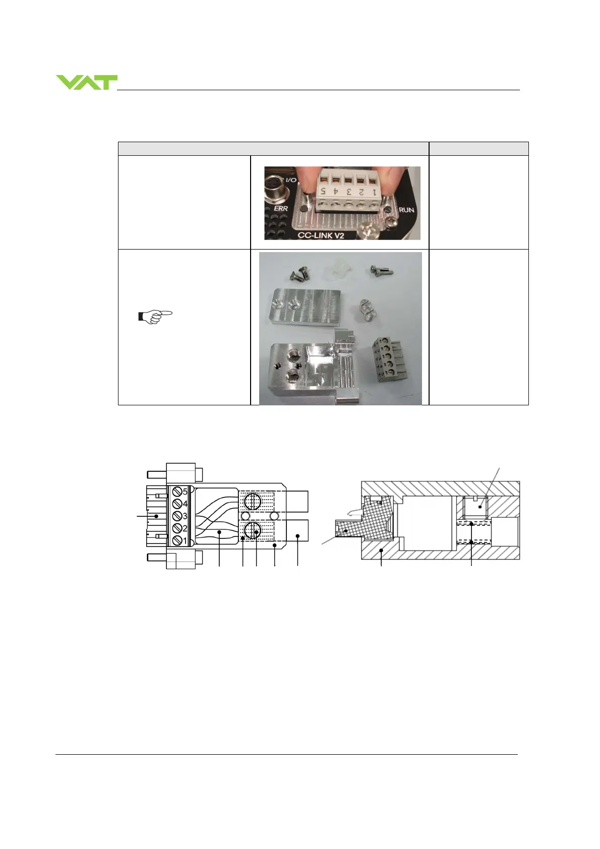
4.5.5.2 Preparing CC-Link connector
1. Remove «COMBICOM»
connector (A) at valve
controller
sample picture
2. Prepare all parts of
connector for installation
All parts of connector are
supplemented in a plastic
bag (407612), except
«COMBICOM» connector
from valve controller
4.5.5.3 CC-Link connector overview
A COMBICON D Strain-relief screw for shield mesh and cable
B CC-Link wires E Connector housing VAT
C Shield mesh F CC-Link cable
A
B
C
D
A
E
D
E
F
C
 Loading...


