44
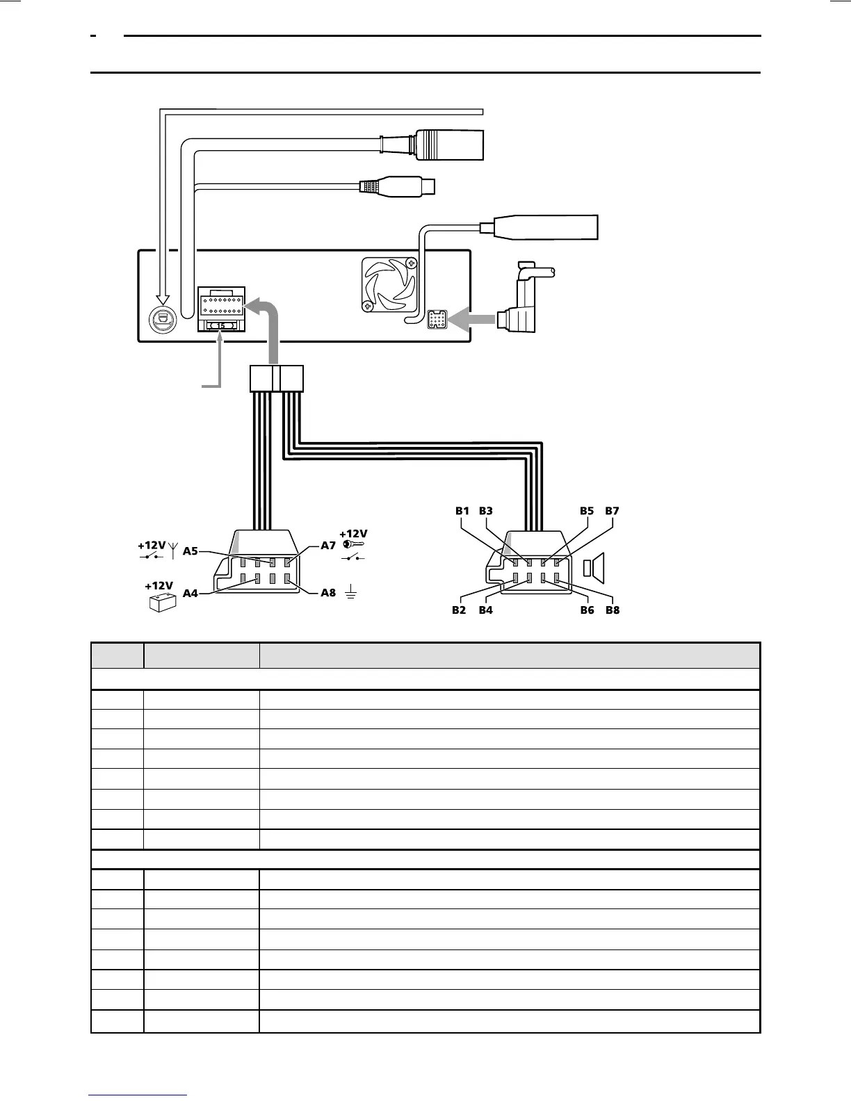
Plug A, power supply
A1 brown Input for telephone mute function
A2 – Not used
A3 – Not used
A4 red + 12 V permanent, must be suitable for 15 A current consumption
A5 blue/white Switch output for automatic antenna (max. 300 mA)
A6 orange/white Input for illumination (e.g. from dipped headlamp)
A7 yellow + 12 V switched (via ignition lock)
A8 black Earth (if no vehicle ISO connection, attach to suitable earthing point on vehicle body)
Plug B, loudspeaker
B1 violet Phase - rear, right (RR +)
B2 violet/black Return line - rear, right (RR –)
B3 grey Phase - front, right (FR +)
B4 grey/black Return line - front, right (FR –)
B5 white Phase - front, left (FL +)
B6 white/black Return line - front, left (FL –)
B7 green Phase - rear, left (RL +)
B8 green/black Return line - rear, left (RL –)
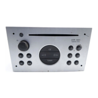
8.WIRING CONNECTIONS
Rear view of main unit
NAVI/CCD connection socket
RGB input socket
VIDEO input socket (for TV tuner)
Antenna socket
Fuse (15A)
Pin no. Wire colour Connection
BUS cable
 Loading...