Initial Setup Of The Console Using Workflow Wizard Setup>Devices
20
Setup>Devices - Continued
PROBE SETUP
Set up each probe being monitored before selecting the next device type.
Configured
Touch the radio button to enable or disable configuration of the selected
probe.
NOTES:
•
Do not enable probe configuration until its address is assigned!
• Once enabled, do not disable a probe if it is assigned to a tank. You must
first unassign the probe from the tank before the probe can be disabled.
(see Setup > Tank > General).
Address
Touch and select the address of this probe.
Label
Touch to enter a description of this probe (up to 20 alphanumeric characters)
that will appear on the console screens and in reports.
Serial Number
[Read Only] Console auto-detected serial number of this device.
Type
[Read Only] Console auto-detected type of this device.
Float Type
Installed Mag probe float type (the console will display only the applicable
float size options for this device). For example, depending on the probe
installed the float sizes below could display in the drop down list:
NOTES:
• Only circuit codes D004, D005 and D006 are allowed to set the float type to
4.0 in phase separation.
• If the probe is changed and the previous float is supported by the new
probe, the float assignment will remain the same. Otherwise the default
float will be assigned to the new probe.
• Only select Custom if the literature that was shipped with probe float kit
specifically states that you must choose this Float Type. Currently only
three mag probes use Custom Float Types: Chem-ISO mag probes, LPG-ISO
mag probes and the Mag-FLEX probe with low level water floats.
When Custom float type is selected, the Fuel Offset, Water Offset, Water
Minimum and Invalid Fuel parameter fields below are enabled for edit.
Refer to the appropriate installation kit manual for these entries (see
“Related Documents” on page 1).
Fuel Offset -Touch to enter the Fuel Offset value listed in the appropriate
kit manual (577013-770, 577013-773 or 577014-056).
Water Offset (Mag-FLEX probes with Low Level Water Float only) -
Touch to enter the Water Offset value listed in the 577014-056 manual.
Water Minimum (Mag-FLEX probes with Low Level Water Float only) -
Touch to enter the Water Minimum value listed in the 577014-056 manual.
Invalid Fuel - Touch to enter the Invalid Fuel value listed in the appropri-
ate kit manual (577013-770, 577013-773 or 577014-056).
Density Code
This field stores specifications for a density probe. It must be exactly 14
characters, and is composed of four parts as described below:
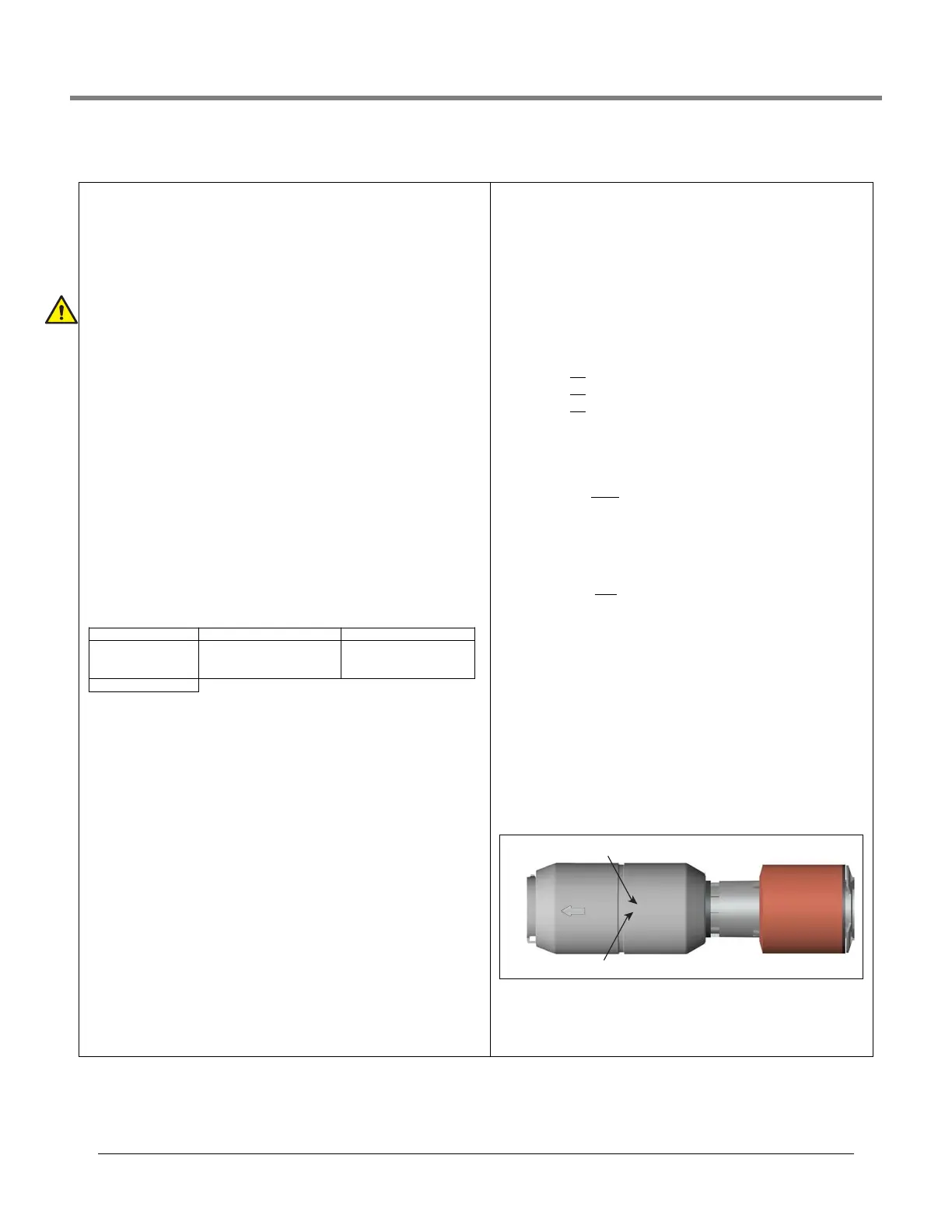
The density code has the following format: FGGGGGGMMMMDDD, e.g.,
B7053686719512, and is impressed in the float body (see image below).
Where:
F = Fuel Type: A for gasoline and B for diesel.
Using the example density code above: B = Diesel, G = Gauss
The last two digits are the gauss readings for each magnet in the den-
sity float. The prefix is always 7 and is omitted from the density code.
Using the example density code above:
70 Gauss = 77.0
for top magnet in grams
53 Gauss = 75.3
for middle magnet in grams
68 Gauss = 76.8 for bottom magnet in grams
M = Mass
The last four digits of the mass of the float. The prefix is always 1 and is
omitted from the density code.
Using the example density code above:
6719 = Mass of 16.719
grams
D = Density of the float
The prefix is dependent on the fuel type and is omitted from the density
code. A = 7 (gasoline) and B = 8 (diesel).
Using the example density code above:
512 = density of 851.2
kg/m
3
for a fuel type of diesel.
NOTE: If you change the Density Code, the Density Offset History is
cleared and current Density Offset is set to zero. See Diagnostics>
Probe>Density Offset screen for details on console density values.
Density Float Serial Number
Touch this field to enter the density float’s serial number.
NOTE: if you change the density float serial number, the Density Offset
History is cleared and the current Density Offset is reset to zero.
The density float serial number has the following format - yywwxxxx,
e.g., 13240161, and is impressed in the float body (see image below).
Where;
YY = the last two digits of the year it was manufactured’
WW = the number of the week it was manufactured,
XXXX = a unique integer for the density float
•4.0in •4.0inphaseseparation •3.0in
•2.0innon‐density
•2.0instandard‐standard
densitywaterfloat(1.5inch
minimumwaterlevel)
•2.0inlowwater‐ lowwater
densitywaterfloat(1inch
minimumwaterlevel)
•Custom
B7053686719512
S/N: 13240161
Example Density Code
Example Serial Number
 Loading...