© by N&W GLOBAL VENDING S.p.A. 22 02-2014 4535 00
FIRST SANITIZATION
When the machine is installed, it is necessary to carry
out a thorough disinfection of food circuits (infuser unit,
mixer, beverage delivery ducts, inner tank,...) to ensure
the hygiene of the products delivered.
Jets of water are to be absolutely avoided for clean-
ing.
The sterilization is performed by means of sterilizing
products.
Wash the mixer by adding a few drops of sanitizing solu-
tion, completely wash the cappuccino maker and the
infuser unit.
Once the sterilisation has been performed, rinse the mix-
ers well for removing any possible residue of the solution
used.
To supply water to the mixer use the rinse function from
the "washes" menu.
Important
The machine is equipped with an automatic wash sys-
tem for the mixers, infuser unit and milk circuit.
If the use of the machine is subject to idle periods (week-
ends, etc.), even for less than two days, it is good prac-
tice to enable the automatic washing functions (before
beginning to use the machine).
OPERATION
ESPRESSO UNIT
After each start-up of the machine, the coee unit per-
forms a full rotation before performing the normal cycle in
order to ensure that the device is positioned in the initial
position.
If a coee-based selection is requested, the grinder is
activated until the coee doser chamber is full.
When the doser is full, the coee dose is released into
the infusion chamber which is located vertically inside
the coee unit.
The gear motor engaged on the pinion lets the cranks ro-
tate, which cause the infusion chamber to rotate as well.
The upper piston aligns itself with the infusion chamber
and descends inside it. The position where the piston
stops for the infusion will depend on the quantity of cof-
fee inside the chamber.
2
1
3
4
5
6
7
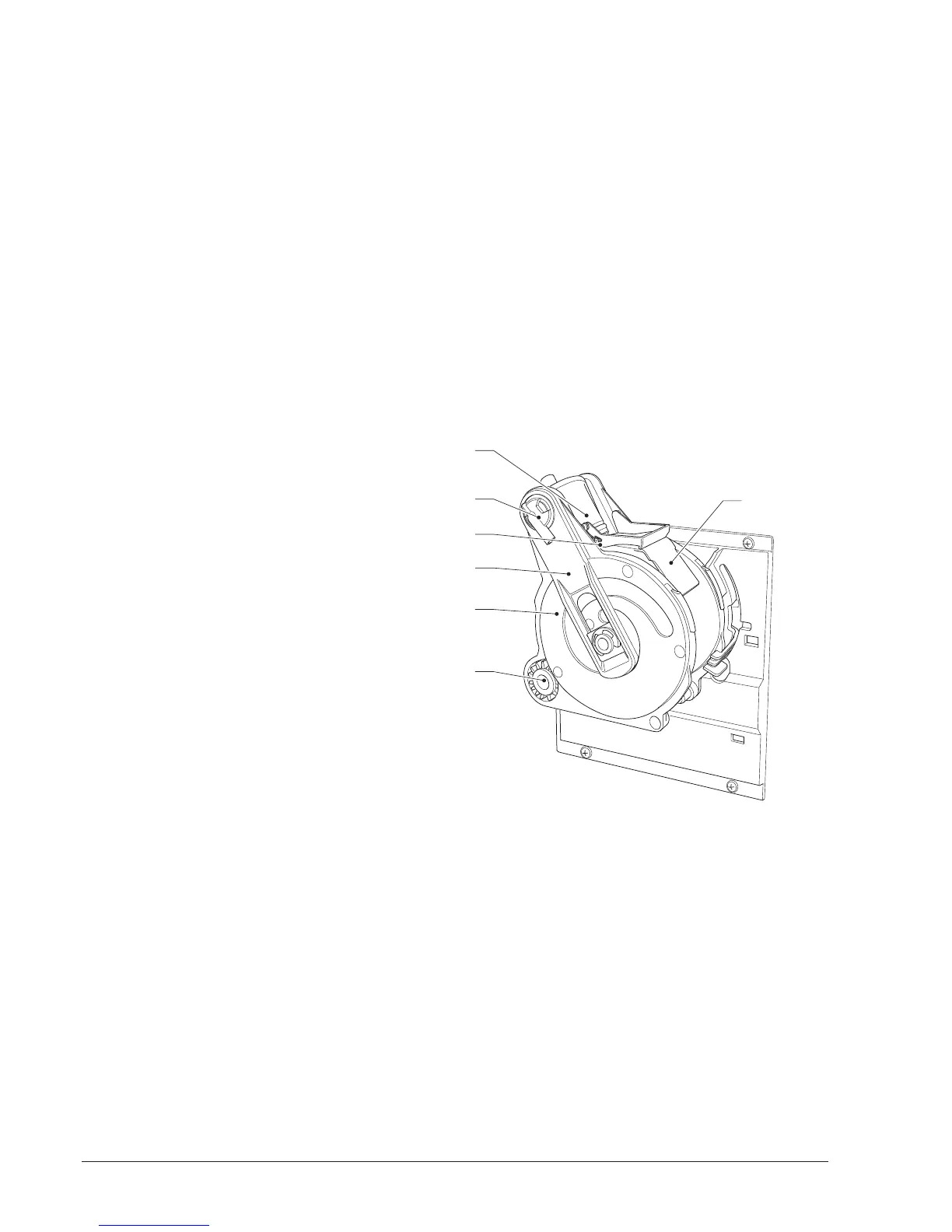
Fig. 22
1- Upper piston
2- Coffee outlet nozzle
3- Scraper
4- Rods
5- Cranks
6- Pinion
7- Exhaust pad slide