2.4 Air-distribution Considerations for Upflow Units
Various configurations are available:
• Front return
• Rear return
• Bottom return(not available onCW106 and CW114 models)
For in-room applications with supply and returngrilles, several feet of clearance must be maintained at the intake and
discharge of the unit.
Upflow rear-returnconfigurations use a filter box attached to the back of the unit. Allow25in. (635mm) onone side of the
unit for access to the rear-returnfilter box. Refer to the rear-return installationsheet, inside the rear-returnfilter box
package.
For ducted applications, duct flanges are supplied onthe blower outlets. Followthe SMACNA-Duct Construction Standard
for single-, dual-, or triple-blower systems. Do not runduct work off the perimeter flange onthe top of the unit. Thisflange is
for positioning and attaching the optional air discharge plenum withgrille. Attaching a duct to this flange may reduce
airflow to inadequate levels.
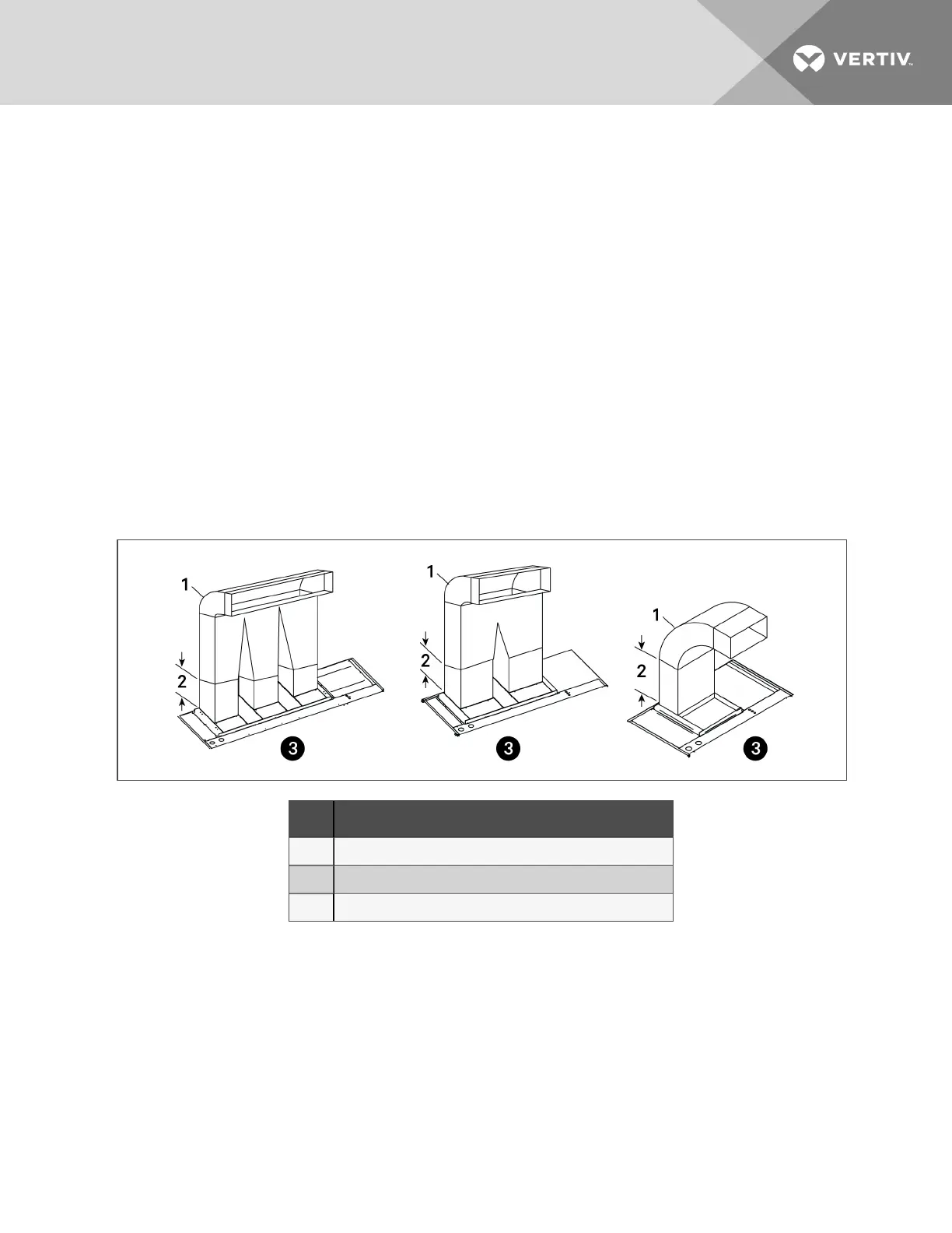
Figure 3.2 Upflow ducting configurations (forward-curved blowers)
Item Description
1 Typical ducting
2 Straightsectionsmustbe 1.5 to2.5 timesthe longest blowerdimension.
3 Front of unit
NOTE: Drain traps are qualified to a return duct static of negative 1.5 i.w.g. (-1.5i.w.g).
2Pre-installation PreparationandGuidelines
19
 Loading...