NOTICE
Risk of improper power-supply connection. Cancause equipment damage and loss of warranty coverage.
Prior to connecting any equipment to a mainor alternate power source (for example: back-up generator
systems) for start-up, commissioning, testing, or normal operation, ensure that these sources are correctly
adjusted to the nameplate voltage and frequency of all equipment to be connected. Ingeneral, power-source
voltages should be stabilized and regulated to within±10%of the load nameplate nominal voltage. Also, ensure
that nothree-phase sources are single-phased at any time.
See transformer label for primary tap connections. Installer will need tochange transformer primary taps if
applied unit voltage is other thanpre-wired tap voltage.
NOTE: Seal openings around piping and electrical connection to prevent air leakage. Failure to do so
could reduce the unit’s cooling performance.
The electrical and unit-to-unit connections are described inthe submittal documents included inthe Submittal Drawings on
page109.
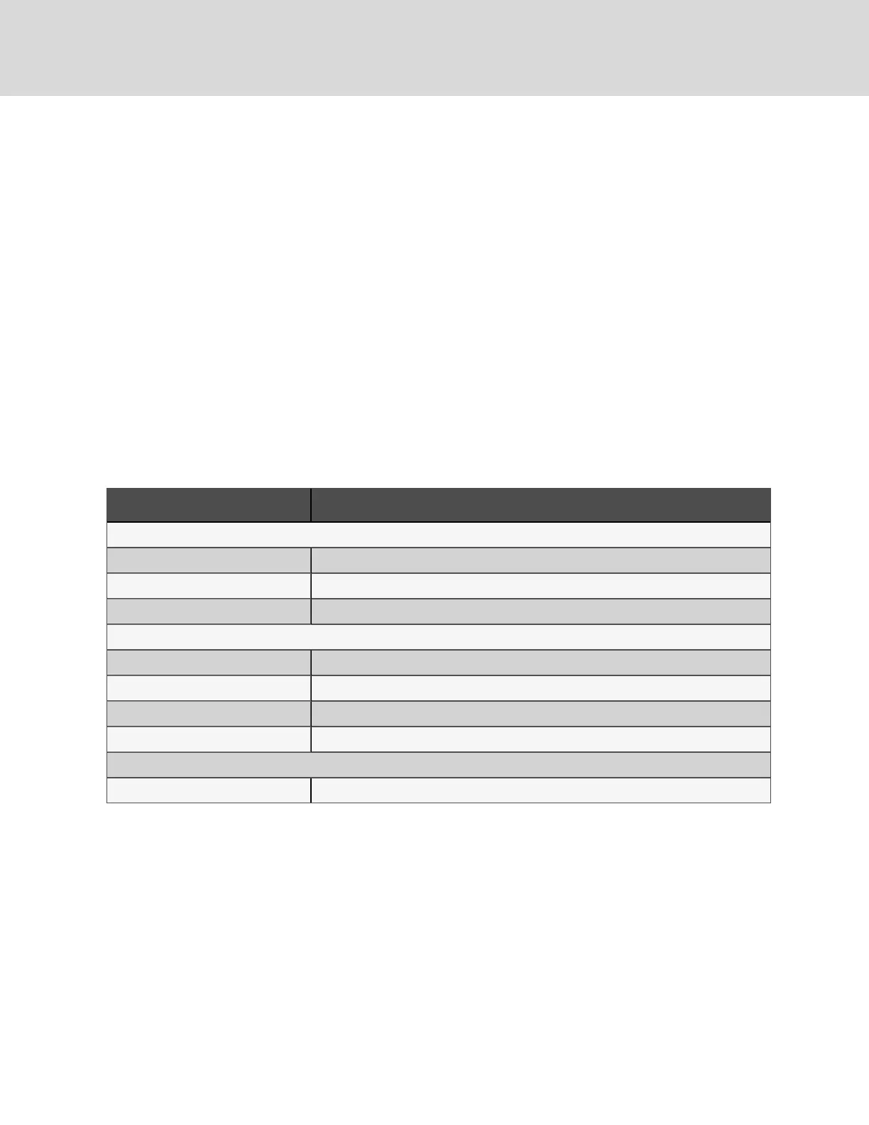
The following table lists the relevant documents by number and title.
Document Number Title
DownflowUnits
DPN004548 Electrical FieldConnections, DownflowCW038toCW084
DPN004549 ElectricalFieldConnections, Downflow, CW106andCW114
DPN004550 Electrical FieldConnections, Downflow, CW146andCW181
UpflowUnits
DPN003200 High-voltage Connections, Upflow, CW038toCW084
DPN004552 Low-voltage andEthernetConnections, Upflow, CW038toCW084
DPN003202 High-voltage Connections, Upflow, CW106andCW114
DPN004551 Low-voltage andEthernetConnection, UpflowCW106andCW114
Unit-to-Unit Networking
DPN004351 Liebert®iCOMUnit-to-unit Network Connections
Table 6.1 Electrical Field-connection Drawings
Vertiv | Liebert® CW™Installer/User Guide
40
 Loading...