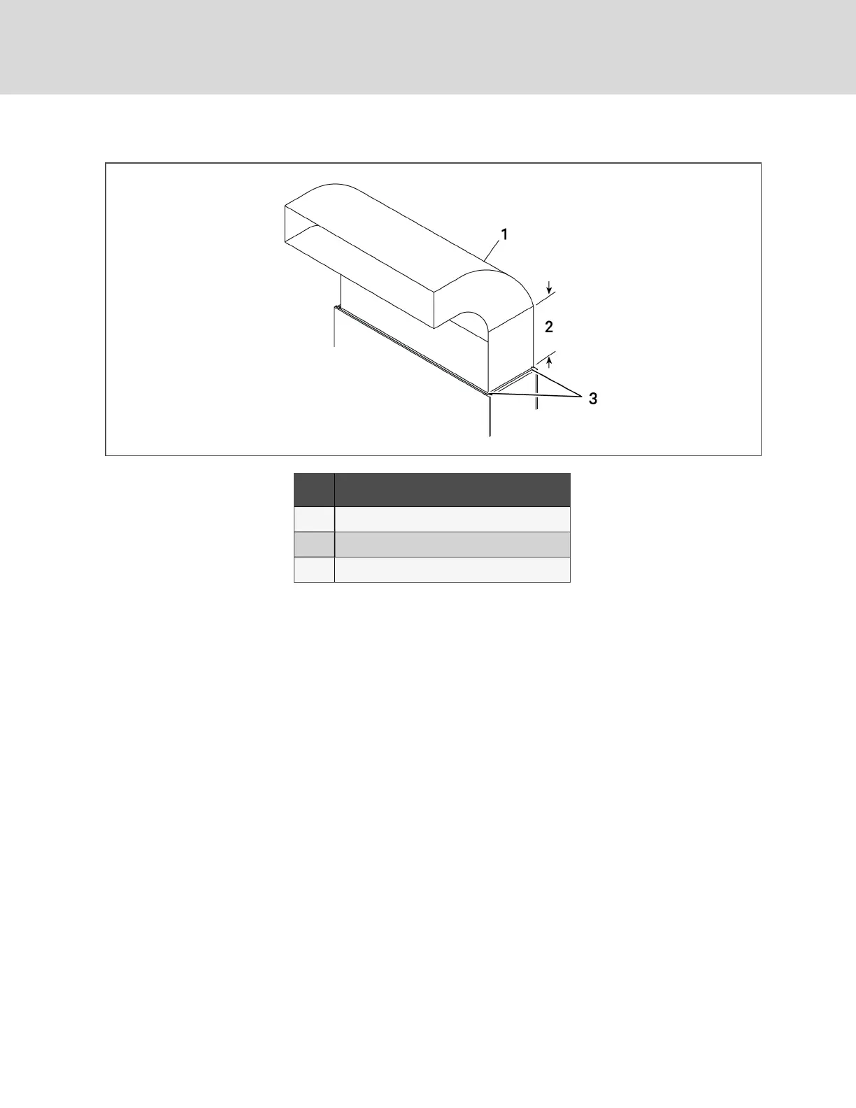
Figure 3.3 Upflow ducting configurations for EC fans
Item Description
1 Typical ducting. May runto either side.
2 Straightsectionmustbe 2.5timesthe depthof blower.
3 Ductingonlyattachedtoflangesonprovidedplenum.
NOTE: Follow standard practices in all duct work.
2.5 Connections and System Setup
• The unit requires a drain, which must comply withall applicable codes. See Field-installed, Gravity-fed Drain
Line Requirements on page33, for details.
• Planthe routing of wiring, piping and duct work tothe unit. Refer to the appropriate piping connectionlocation
drawings, piping schematics, and electrical-connection drawings for your system inSubmittal Drawings on
page109.
• If seismic requirements apply, consult your Vertiv representative for informationabout a seismic-rated floor
stand.
NOTE: Seal openings around piping and electrical connection to prevent air leakage. Failure to do so
could reduce the unit’s cooling performance.
2.6 Operating Conditions
The Liebert® CWmust be operated ina conditioned space withinthe operating envelope that ASHRAE recommends for
data centers. The ASHRAE recommended maximum dew point is 59°F (15°C). Operating the CWoutside of this envelope
candecrease equipment reliability. Refer to ASHRAE’spublication, “Thermal Guidelines for Data Processing Environments.”
Vertiv | Liebert® CW™Installer/User Guide
20
 Loading...