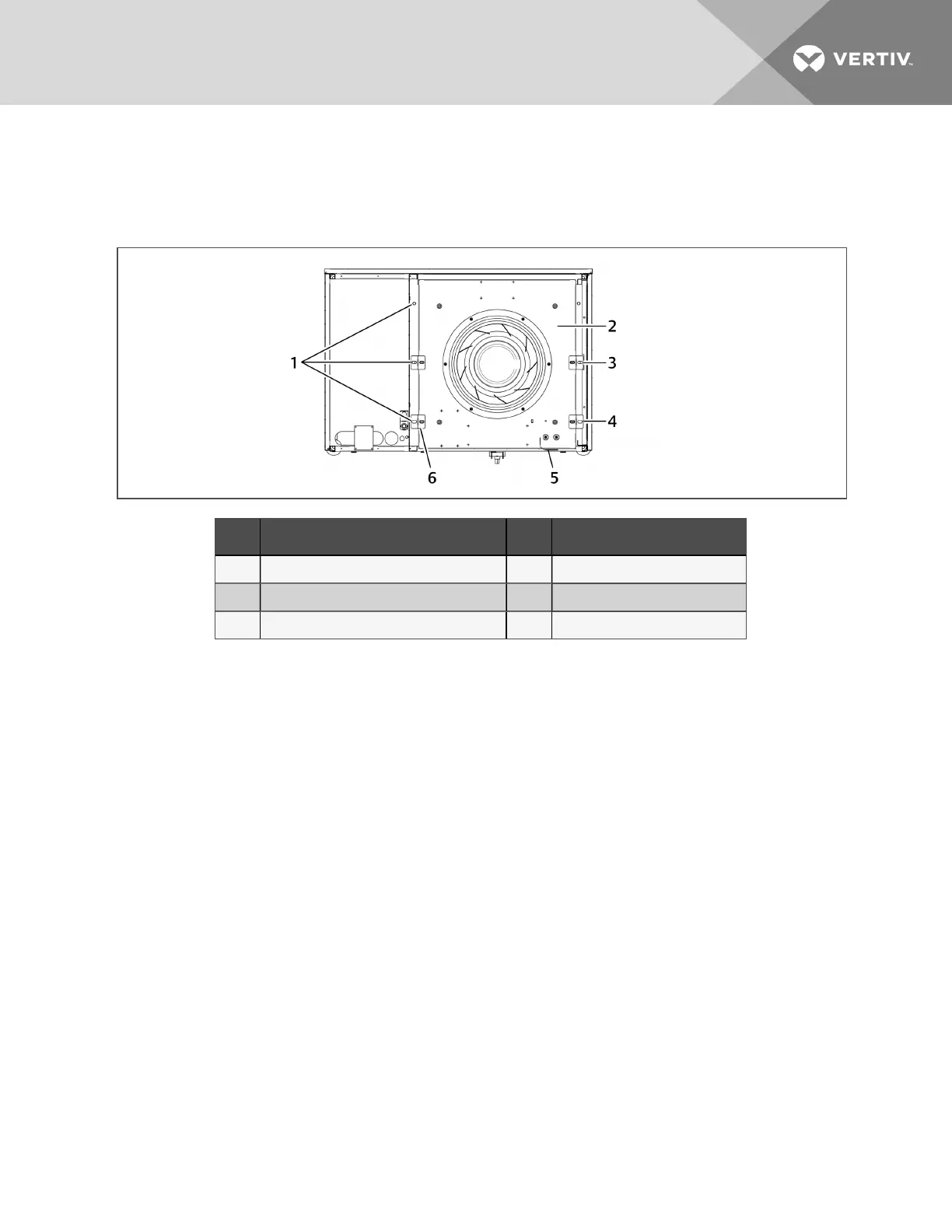
4. Remove hardware, Figure 11.3 below, that retains the fanin the lowered position, and save it forre-installation.
NOTE: Hardware quantity and location varies depending on the type of unit.
Figure 11.3 Hardware removal
Item Description Item Description
1 1/2-in. (13-mm)Hex-headbolts(typical bothsides) 4 Z bracket locationonCW076toCW114
2 Fandeck 5 Wiringloop
3 Z bracket locationonCW038toCW0060 6 Z bracket
5. Use the jack toraise the fanmodule slowly until the fan motor clears the front frame channel.
6. Insert a field-supplied fan-removal device securely onthe front and rear frame channels under the fanmodule
as shown inFigure 11.4 onthe next page.
• A suitable fan-removal device is twolengthsof rigid material that is 4 inches (100mm) wide and strong
enoughto support the weight of the fanmodule.
10 Maintenance
91
 Loading...