5.3 Machine installation (schema)
You can either use the switching unit including
the control cable or the data cable of supported
suction units. The data cable must be provided
by the manufacturer of the suction unit.
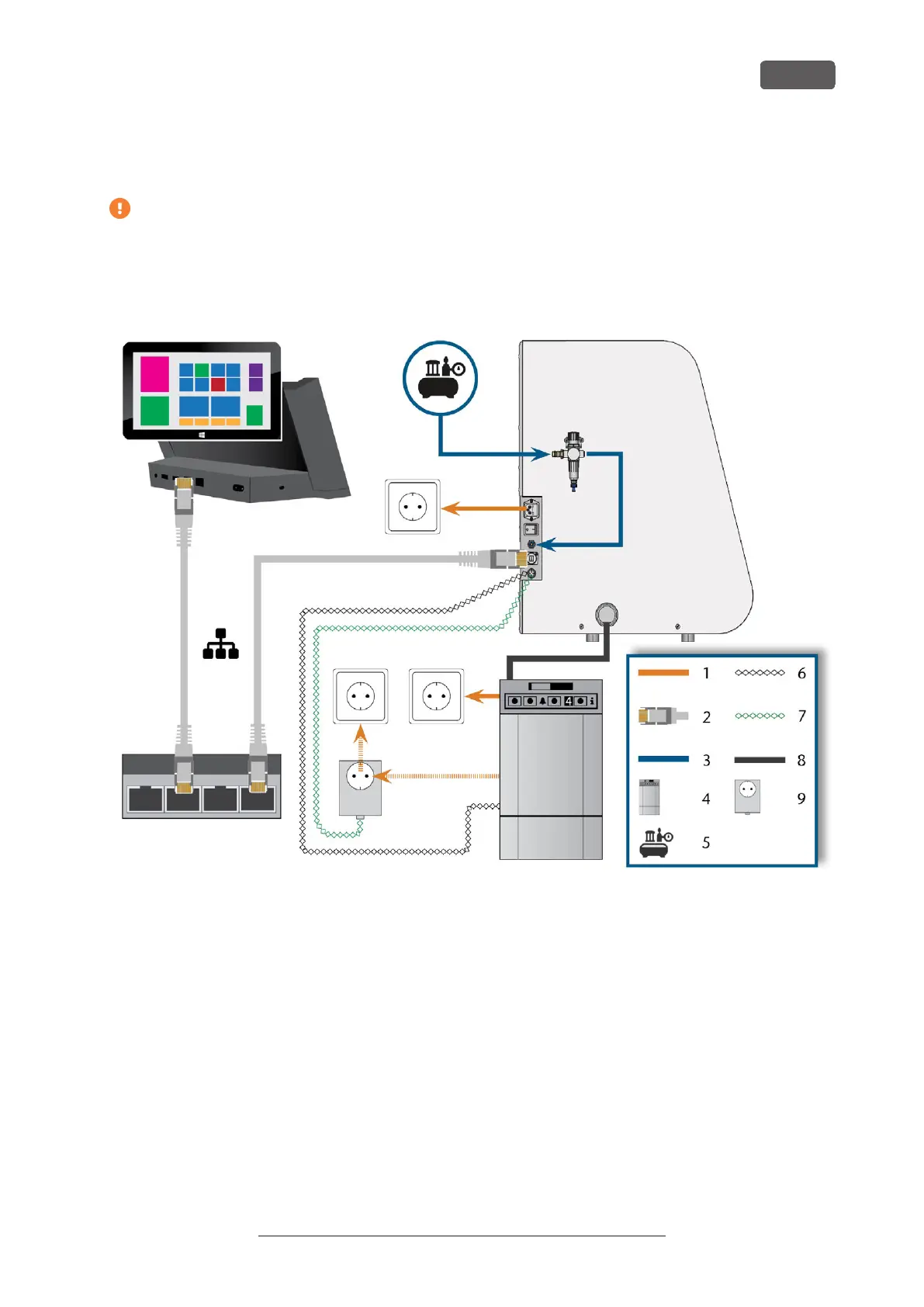
FIG. 11 MACHINE INSTALLATION (SCHEMA)
1. Power connection
2. Ethernet network cable
3. Pneumatic hose
4. Suction unit
5. External compressed air supply
6. Data cable of supported suction units (optional)
7. Control cable of the switching unit (optional)
8. Suction hose
9. Switching unit (optional)
K5+ – Installing the machine
EN 17
Original Operating Instructions:K5+
Version: 12/16/2021