Assignment Variant 2 (SPM-16A-FASS)
NOTICE
When using the safety circuit please observe that the door circuit as well as the
emergency stop circuit must be connected with a double-pole switch.
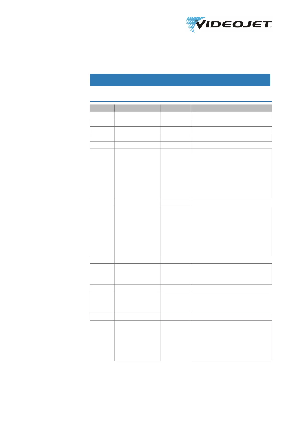
Terminal Signal In/Output Description
X9.1 24V_INT Output see X9.23
X9.2 GND_INT Output -
X9.3 - Input -
X9.4 GND_INT Output -
X9.5 24V_INT Output -
X9.6 RELEASE DOOR
RELAY 1
Output Extension to switch off additional
relays if door circuit is opened.
Using the contact extension no
more than 50 mA per relay may be
drawn. Flyback diodes must be
used and the feedback circuits
must be wired according to the
sample wiring.
X9.7 24V_INT Output -
X9.8 RELEASE DOOR
RELAY 2
Output Extension to switch off additional
relays if door circuit is opened.
Using the contact extension no
more than 50 mA per relay may be
drawn. Flyback diodes must be
used and the feedback circuits
must be wired according to the
sample wiring.
X9.9 GND_INT Output -
X9.10 DOOR FEEDBACK
IN
Input Feedback input for forceguided
contacts of the extension relays.
Default: Bridge to X9.12
X9.11 GND_INT Output
X9.12 DOOR FEEDBACK
OUT
Output Feedback output for forceguided
contacts of the extension relays.
Bridge to X9.10
X9.13 - Input
X9.14 DOOR 1 IN Input If one of the door circuits is
opened, the beam shutter of the la-
ser is closed immediately.
Connect to X9.7 to close the door
circuit.
Default: Bridge to X9.7
09/17 - Index: AD [EN]
66
Videojet 3140/3340/3640/8 Appendix