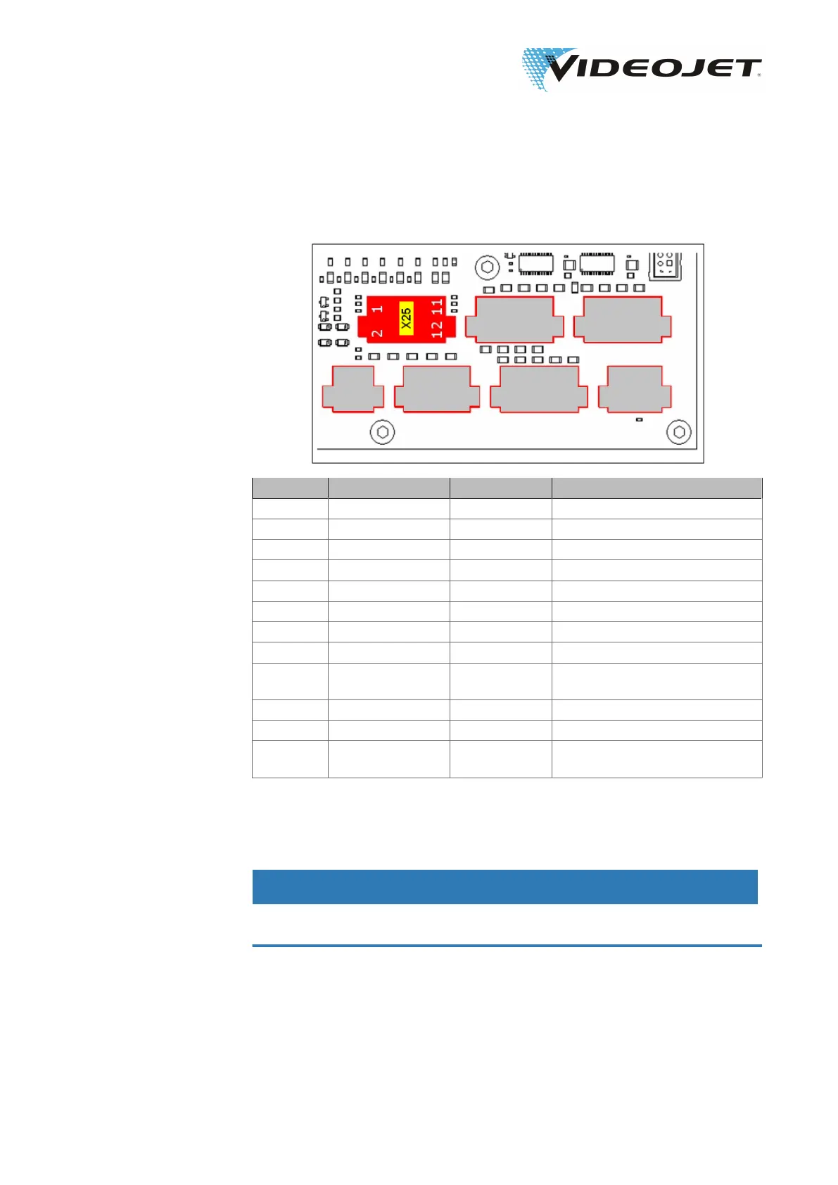
8.3.6 Assignment of Connector X25 Encoder/Product
Detector
Terminal Signal In/Output Description
X25.1 CHA Input Input for track 1 of encoder
X25.2 CI line supply 0 Output 24 V for encoder
X25.3 CHB Input Input for track 2 of encoder
X25.4 CI line supply 1 Output 24 V for trigger
X25.5 IN_ENC_IDX Input Input for index track of encoder
X25.6 GND_CI Output GND
X25.7 TRG Input Input trigger (product detection)
X25.8 GND_CI Output GND
X25.9 CI line 4 Output Trigger enable (bridge to
X25.12)
X25.10 GND_CI Output GND
X25.11 reserved Output
X25.12 24 V CI Output Voltage supply 24 V (bridge to
X25.9)
The encoder and the product detector are to be connected as shown in the figure
below.
min. pulse length 2 µs
min. load 20 mA
NOTICE
If both tracks of the encoder are used the value for pulses per rotation must be
doubled in the product registration.
09/17 - Index: AD [EN]
77
Videojet 3140/3340/3640/8 Appendix