Document: LT0439 Vigilant MX1-Au Operator Manual
Issue 1.73 23 October 2018 Page 11-13
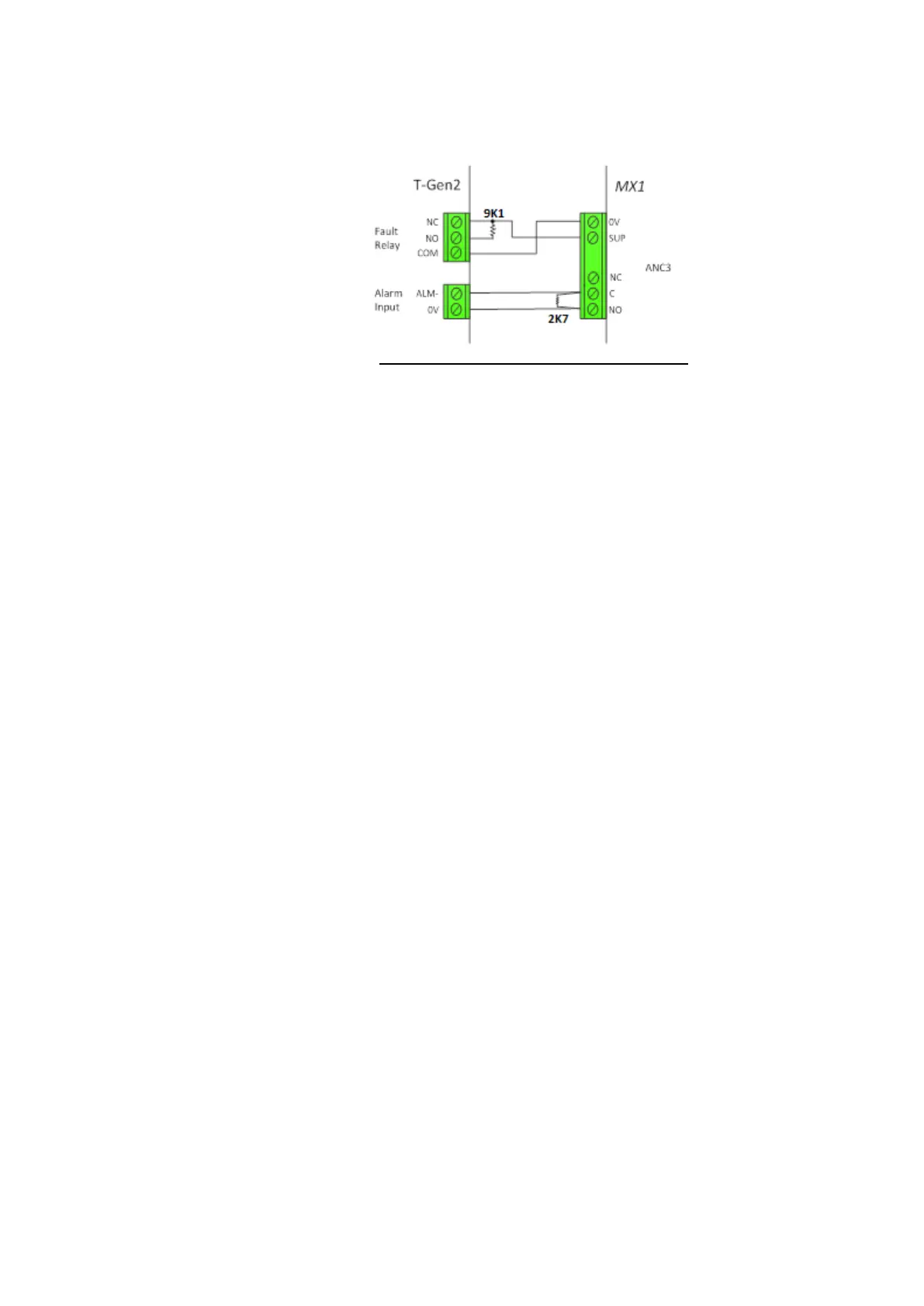
A T-Gen2 can be controlled by the MX1 ANC3 relay, using the wiring
shown in Figure 11-9c. ANC3 supervision is set to “ANC3”.
Figure 11-9c – T-Gen2 Wiring Using ANC3
A Grade 2 solution requires the T-Gen2 to be powered from a separate
PSE. FP1139 - 14A PSE provides a fully compliant solution. FP1129 and
FP1130 provide optional expansion if required.
For a Grade 2 multi-zone installation there are 3 options to implement the
zone selection:
1) Use the 16-way relay expansion board PA0470 that can be
connected to the MX1 LCD/Keyboard and wired to the General
Purpose Input connections of the T-Gen2.
2) Use the T-Gen2 HLI board (FP1143) to interface both units, see
RZDU section in this document.
3) When no other RZDU devices are present, then a direct RZDU
connection between the MX1 panel and T-Gen2 is possible, see
RZDU section in this document.
The MX1 gear plate has five holes for plastic standoffs and one metal
standoff to mount a T-GEN 50 tone generator.
The T-GEN 50 can be connected to the ANC1 relay output as shown in
Figure 11-10, using the pre-made loom (LM0319) included for this
purpose. It plugs in to the 6 way header on ANC1.
When using FP0698, which has the T-GEN 50 mounted on a hinged 3U
Panel with integral PA microphone, this has a pre-made 1.3 metre loom
which plugs into the 6 way header on ANC1 in place of LM0319.
This wiring provides complete supervision of wiring open and short
circuits, as well as passing the state of the T-GEN 50’s fault relay to the
MX1 controller. The 10k resistor is critical to this supervision and
should not be omitted, or a different value substituted.
ANC2 could be used to control the T-GEN 50 instead of ANC1, but this
will require manual wiring as the supplied loom supports only ANC1.
When the T-GEN 50 Alert and Evacuation tones must be separately
controlled by the MX1, one of the GP OUT terminals can be connected to
the T-GEN 50’s A/I/E- input, as shown in the diagram. This is not default
operation, and the MX1 must be specially configured.