Vigilant MX1-Au Operator Manual Document: LT0439
Page 23 October 2018 Issue 1.73
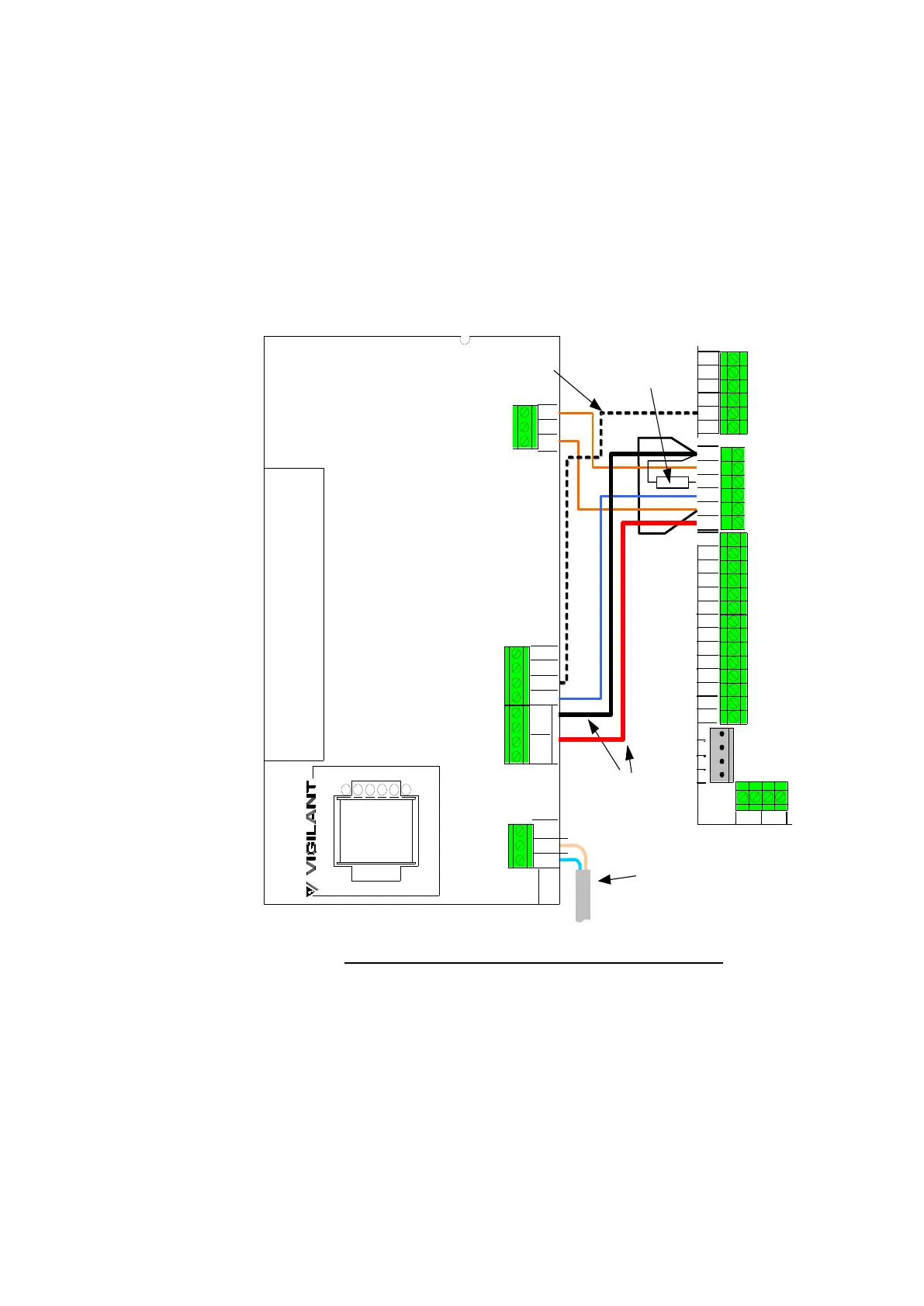
The metal standoff mounting the T-GEN 50 provides the necessary
protection earthing. No other earth lead is required.
Refer to the T-GEN 50 Installation Manual (LT0186) for information about
its DIP switch and link settings, but the following settings are required at
least:
SW4 = ON, to enable Alarm Input supervision
SW5=OFF, for non-latching ALM
LK7 = RELAY, to enable the Fault Relay output
LK2 and LK6 = MASTER
10k ohm
resistor
100V a.c.
telecommunication LV
cable – keep separate from
Power LV and ELV cables
Optional
connection for
separate control
of Alert and Evac
tones
1.0mm
2
stranded or
heavier
0V
SUP
NC
C
VBF
+
NO
VBF
+
OUT
1
OUT
2
LINE -
LINE +
EARTH
SIG
DEF-
COM
NC
NO
FAULT RELAY
OUTPUT
A/I/E -
ALM -
0V
0V
+24V
+24V
DC INPUT
M
X1 CONTROLLER
T-GEN50
ANC RELAY 3
ANC RELAY 2
ANC RELAY 3
Figure 11-10 – Wiring Ancillary Relay 1 to T-GEN 50
Mini-Gen is an alternative tone generator to T-Gen2 and T-GEN 50, but
with lower power and fewer facilities.
The MX1 gear plate has four mounting footprints for mini-Gens, two of
which overlap with the T-Gen2 / T-GEN 50 footprint. The first min-Gen
should be mounted in the lower position. Earth this first mini-Gen to the
gear plate using the nearby M3 metal stand-off and an M3 screw (a
LM0231 200mm earth loom is included in MX1). The second and third
Mini-Gens are mounted on plastic standoffs, and should be earthed to
the first Mini-Gen as shown in Figure 11-11.