Chapter 1 Basics and Assembly Manual VIPA System 200V
1-4 HB97E - CPU - RE_21x-1Bx06 - Rev. 13/20
PS 207/2
X2
34
VIPA 207-1BA00
L
N
P
E
100-240V AC
550-230mA
50-60Hz
OH
OL
OK
X1
1
2
3
4
+
-
+
-
OUT DC 24V /
∑Ι:
2A
4A (peak)
G
DC 24V
DC 24V
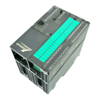
With the System 200V the DC 24V power
supply can take place either externally or
via a particularly for this developed power
supply.
The power supply may be mounted on the
profile rail together with the System 200V
modules. It has no connector to the back-
plane bus.
CM 201
VIPA 201-1AA00
X2
34
X2.X1.
The expansion modules are complemen-
tary modules providing 2- or 3wire con-
nection facilities.
The modules are not connected to the
backplane bus.
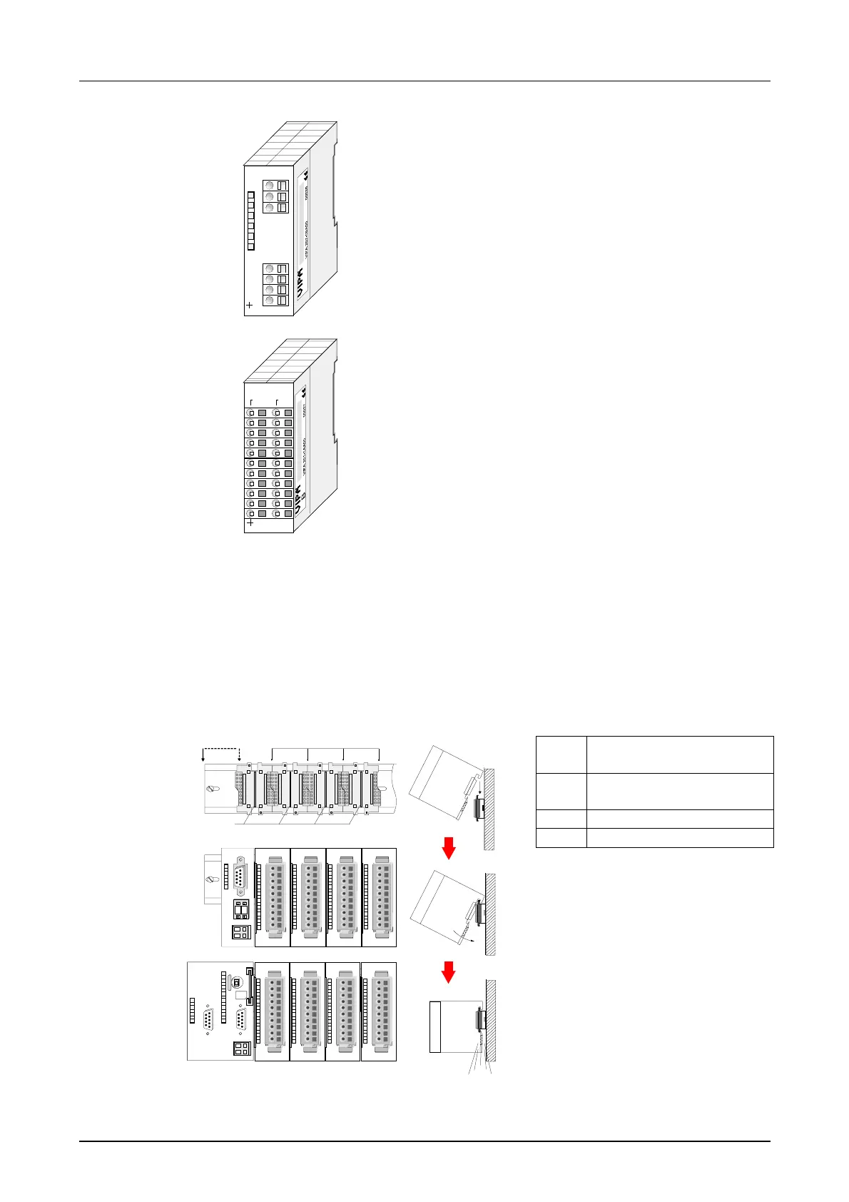
• Profile rail 35mm
• Dimensions of the basic enclosure:
1tier width: (HxWxD) in mm: 76x25.4x74 in inches: 3x1x3
2tier width: (HxWxD) in mm: 76x50.8x74 in inches: 3x2x3
Please note that you can only install header modules, like the CPU, the PC
and couplers at slot 1 or 1 and 2 (for double width modules).
[1] Head module
(double width)
[2] Head module
(single width)
[3] Periphery module
[4] Guide rails
1
2
4
3
0
1
Clack
D
P
Note
A maximum of 32 modules can
be connected at the back plane
bus. Take attention that here the
maximum sum current of 3.5A
is not exceeded.
Please install modules with a
high current consumption direct-
ly beside the header module.
Power supplies
Expansion
modules
Structure/
dimensions
Installation