Manual VIPA System 200V Chapter 1 Basics and Assembly
HB97E - CPU - RE_21x-1Bx06 - Rev. 13/20 1-3
System conception
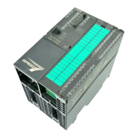
The System 200V is a modular automation system for assembly on a
35mm profile rail. By means of the peripheral modules with 4, 8 and 16
channels this system may properly be adapted matching to your
automation tasks.
PW
SF
FC
MC
CPU 215
DC
24V
+
-
1
2
RN
ST
MR
X1
MMC
R
S
X2
34
VIPA 215-1BA03
M
P
I
2
DI 8xDC24V
SM 221
.0
.1
.2
.3
.4
.5
.6
.7
VIPA 221-1BF00
X2
34
1
2
3
4
5
6
7
8
9
I0
DI 8xDC24V
SM 221
.0
.1
.2
.3
.4
.5
.6
.7
VIPA 221-1BF00
X2
34
1
2
3
4
5
6
7
8
9
I0
DI 8xDC24V
SM 221
.0
.1
.2
.3
.4
.5
.6
.7
VIPA 221-1BF00
X2
34
1
2
3
4
5
6
7
8
9
I0
DI 8xDC24V
SM 221
.0
.1
.2
.3
.4
.5
.6
.7
VIPA 221-1BF00
X2
34
1
2
3
4
5
6
7
8
9
I0
The System 200V consists of the following components:
• Head modules like CPU and bus coupler
• Periphery modules like I/O, function und communication modules
• Power supplies
• Extension modules
CPU 214
M
P
I
PW
SF
FC
MC
R
S
RN
ST
MR
MMC
2
1
2
-
DC
24V
+
X1
VIPA 214-1BC03
X2
34
PW
ER
RD
DE
IM 253DP
ADR.
X8
910
VIPA 253-1DP00
+
-
1
2
DC
24V
X1
D
P
99
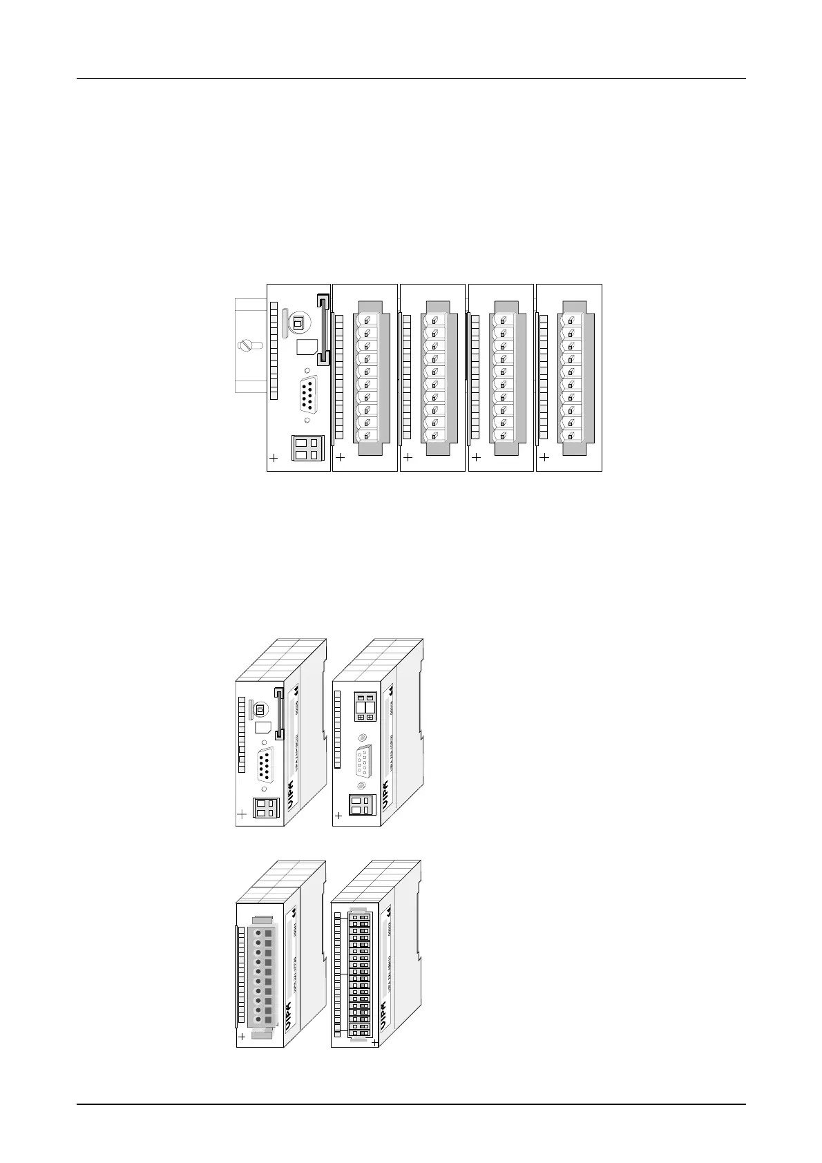
With a head module CPU respectively bus
interface and DC 24V power supply are
integrated to one casing.
Via the integrated power supply the CPU
respectively bus interface is power
supplied as well as the electronic of the
connected periphery modules.
.0
.1
.2
.3
.4
.5
.6
.7
.0
.1
.2
.3
.4
.5
.6
.7
1
2
3
4
5
6
7
8
9
10
11
12
13
14
15
16
17
18
VIPA 221-1BH10
X2
3
4
DI 16xDC24V
n+1
n
DI 8xAC/..48V
SM 221
.0
.1
.2
.3
.4
.5
.6
.7
N
VIPA 221-1FF30
X2
3
4
1
2
3
4
5
6
7
8
9
I0
1
2
3
4
5
6
7
8
9
10
The modules are direct installed on a
35mm profile rail and connected to the
head module by a bus connector, which
was mounted on the profile rail before.
Most of the periphery modules are
equipped with a 10pin respectively 18pin
connector. This connector provides the
electrical interface for the signaling and
supplies lines of the modules.
Overview
Components
Head modules
Periphery modules