Chapter 3 Deployment CPU 21x-1Bx06 Manual VIPA System 200V
3-24 HB97E - CPU - RE_21x-1Bx06 - Rev. 13/20
Factory reset
With the following proceeding the internal RAM of the CPU is completely
deleted and the CPU is reset to delivery state.
Please note that here also the MPI address is reset to the address 2!
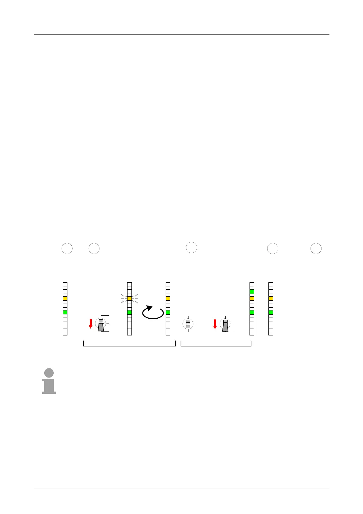
1. Switch the CPU to STOP.
2. Push the operating mode switch down to position MR for 30s. Here the
S LED flashes. After a few seconds the stop LED changes to static
light. Now the S LED changes between static light and flashing. Starting
here count the static light states of the S LED.
3. After the 6. static light release the operating mode switch and tip it
downwards to MR. Now the RUN LED lights up once. This means that
the RAM was deleted completely.
4. For the confirmation of the resetting procedure the LEDs PW and S are
on.
5. Then you have to switch the power supply off and on.
The proceeding is shown in the following Illustration:
RN
ST
MR
30 Sec.
Tip
R
S
PW
SF
FC
MC
CPU in
STOP
Request factory reset
Start factory reset
Factory reset
executed
1
3
R
S
PW
SF
FC
MC
R
S
PW
SF
FC
MC
6x
RN
ST
MR
RN
ST
MR
Tip
1 Sec.
2 4
Power
OFF/ON
5
R
S
PW
SF
FC
MC
R
S
PW
SF
FC
MC
Note!
After the firmware update you always should execute a Factory reset.
Proceeding