Chapter 2 Hardware description Manual VIPA System 200V
2-2 HB97E - CPU - RE_21x-1Bx06 - Rev. 13/20
Properties
• Instruction set compatible with Siemens STEP
7
• Configuration by means of the Siemens SIMATIC manager respectively
TIA Portal
• Integrated V-Bus controller for controlling System 200V peripherals
• Integrated 24V power supply
• Total address range: 1024Byte inputs, 1024Byte outputs
(128Byte process image each)
• 48...128kByte of work memory "on board"
• 80…192kByte of load memory "on board"
• MMC slot (for user program)
• Battery backed clock
• MP
2
I interface for data transfer
• Status LEDs for operating mode and diagnostics
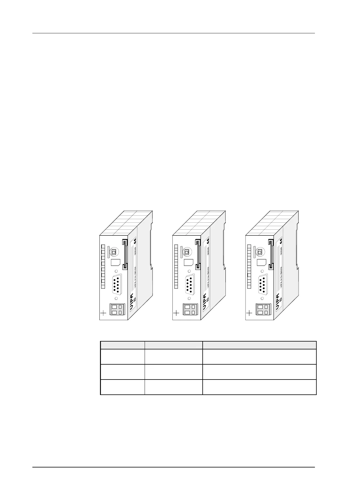
CPU 214
M
P
I
PW
SF
FC
MC
R
S
RN
ST
MR
MMC
2
1
2
-
DC
24V
+
X1
VIPA 214-1BC06
X2
34
CPU 214
M
P
I
PW
SF
FC
MC
R
S
RN
ST
MR
MMC
2
1
2
-
DC
24V
+
X1
VIPA 214-1BA06
X2
34
CPU 215
M
P
I
PW
SF
FC
MC
R
S
RN
ST
MR
MMC
2
1
2
-
DC
24V
+
X1
VIPA 215-1BA06
X2
34
Type Order number Description
CPU 214C VIPA 214-1BC06 PLC CPU 214 with
48/80kByte of work/load memory
CPU 214 VIPA 214-1BA06 PLC CPU 214 with
96/144kByte of work/load memory
CPU 215 VIPA 215-1BA06 PLC CPU 215 with
128/192kByte of work/load memory
CPU 21x-1Bx06
Order data