Chapter 1 Basics and Assembly Manual VIPA System 200V
1-12 HB97E - CPU - RE_21x-1Bx06 - Rev. 13/20
Wiring
Most peripheral modules are equipped with a 10pole or a 18pole connector.
This connector provides the electrical interface for the signaling and supply
lines of the modules.
The modules carry spring-clip connectors for interconnections and wiring.
The spring-clip connector technology simplifies the wiring requirements for
signaling and power cables.
In contrast to screw terminal connections, spring-clip wiring is vibration
proof. The assignment of the terminals is contained in the description of the
respective modules.
You may connect conductors with a diameter from 0.08mm
2
up to 2.5mm
2
(max. 1.5mm
2
for 18pole connectors).
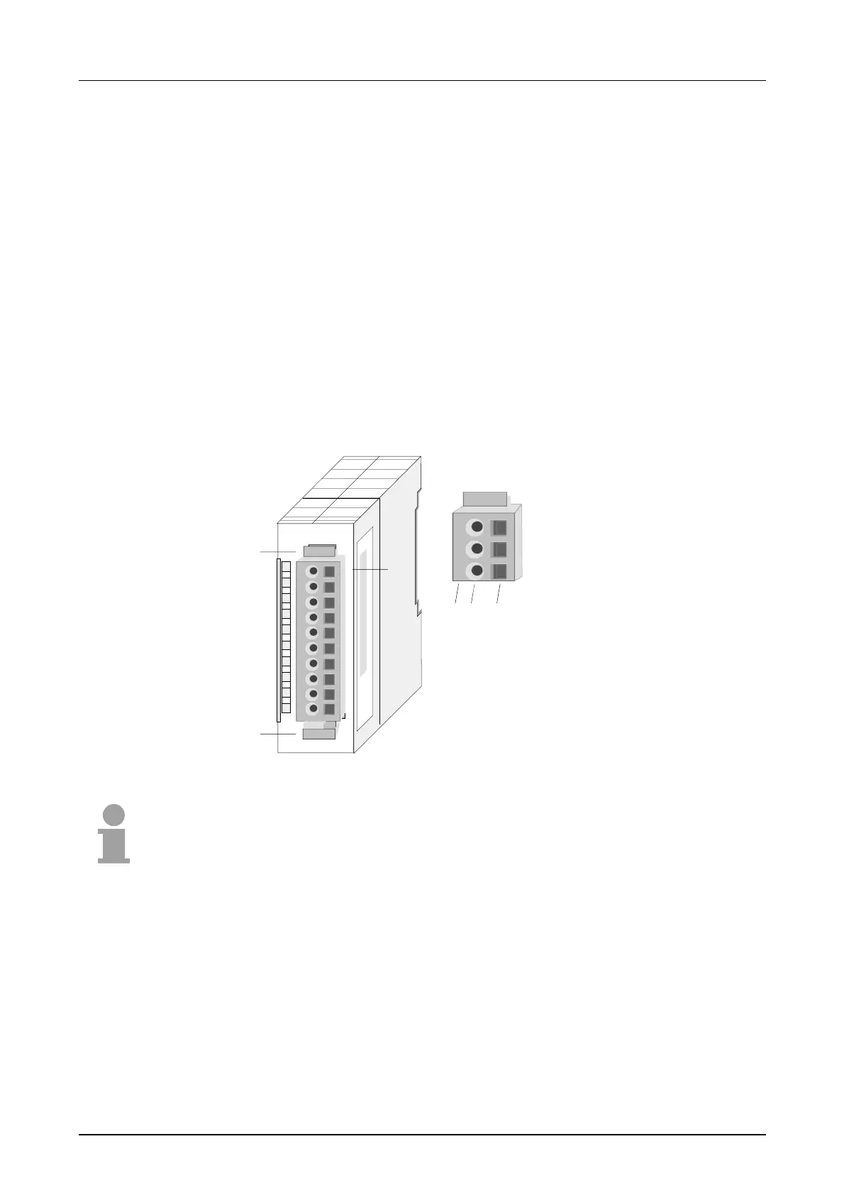
The following figure shows a module with a 10pole connector.
1
2
3
4
5
6
7
8
9
10
1
2
3
3 4 5
1
1
1
2
3
4
5
6
7
8
9
10
2
[1]
[2]
[3]
[4]
[5]
Locking lever
Pin no. at the module
Pin no. at the connector
Wiring port
Opening for screwdriver
Note!
The spring-clip is destroyed if you push the screwdriver into the wire port!
Make sure that you only insert the screwdriver into the square hole of the
connector!
Overview