Manual VIPA System 200V Chapter 1 Basics and Assembly
HB97E - CPU - RE_21x-1Bx06 - Rev. 13/20 1-13
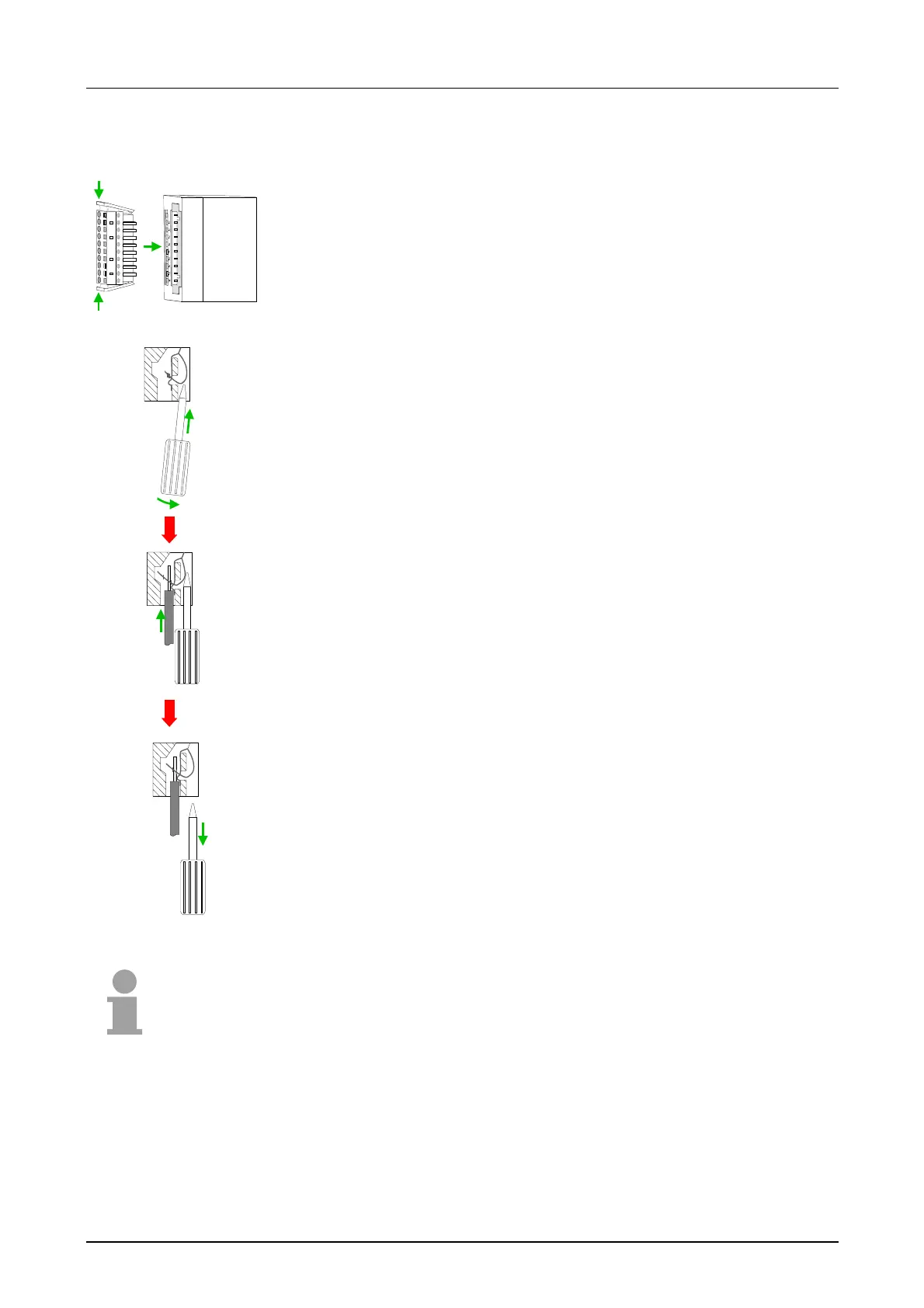
• Install the connector on the module until it locks with an audible click.
For this purpose you press the two clips together as shown.
The connector is now in a permanent position and can easily be wired.
The following section shows the wiring procedure from top view.
• Insert a screwdriver at an angel into the square opening as shown.
• Press and hold the screwdriver in the opposite direction to open the
contact spring.
• Insert the stripped end of the wire into the round opening. You can use
wires with a diameter of 0.08mm
2
to 2.5mm
2
(1.5mm
2
for 18pole connectors).
• By removing the screwdriver the wire is connected safely with the plug
connector via a spring.
Note!
Wire the power supply connections first followed by the signal cables
(inputs and outputs).
Wiring procedure