Manual VIPA System 200V Chapter 3 Deployment CPU 21x-1Bx06
HB97E - CPU - RE_21x-1Bx06 - Rev. 13/20 3-9
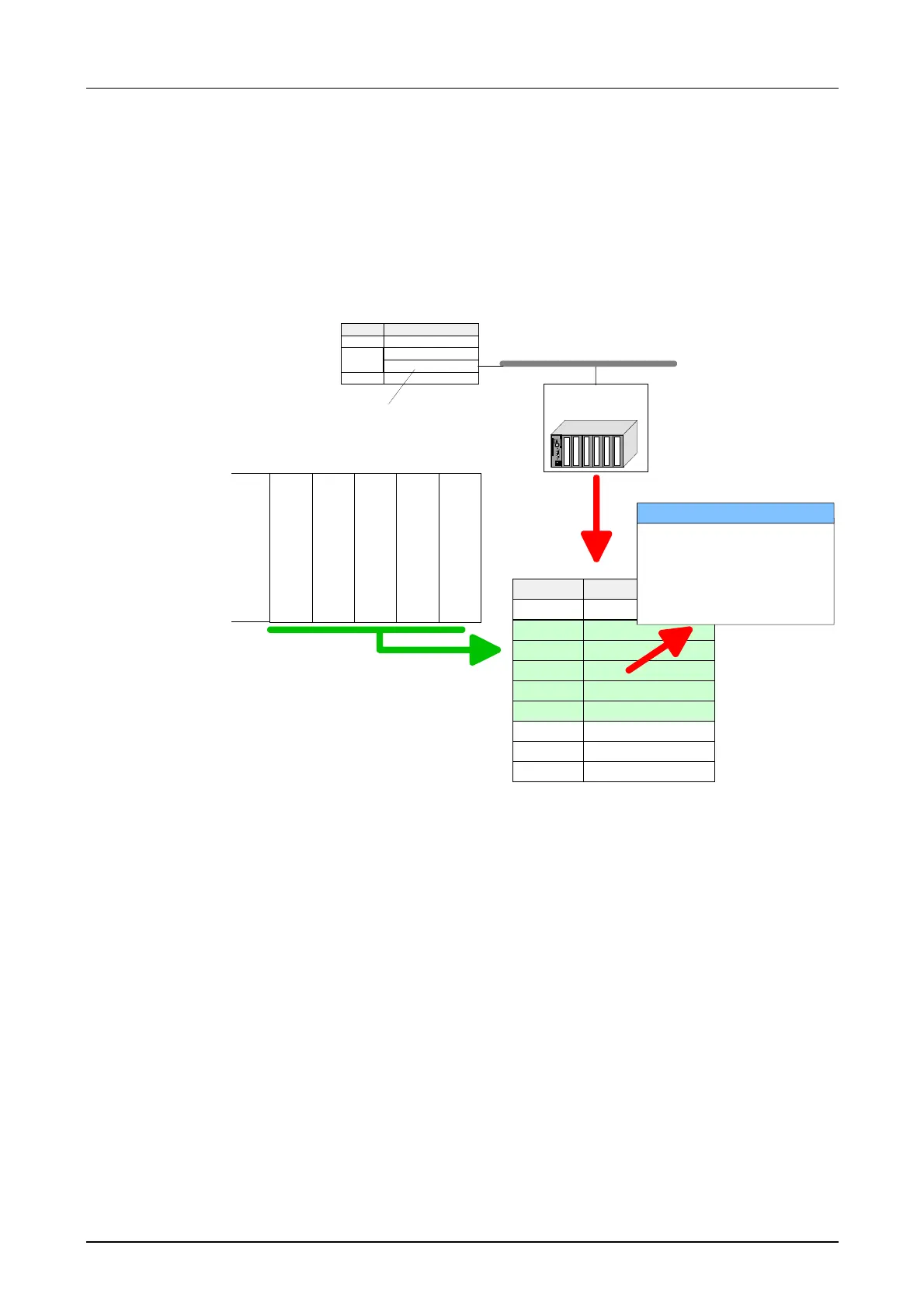
Hardware configuration - I/O modules
After the hardware configuration of the CPU place the System 200V
modules in the plugged sequence.
In order to address the installed peripheral modules individually, specific
addresses in the CPU have to be assigned to them.
Modul
CPU
DI
DO
DIO
AI
AO
Slot
1
2
3
4
5
6
7
8
...
Parameter DIO
Param : .........
Param : .........
Param : .........
Param : .........
Param : .........
Param : .........
Param : .........
Param : .........
DI 8xDC24V
DO 8xDC24V
DIO 8xDC24V
AI 4x12Bit
AO 4x12Bit
CPU 21x
PB-
Addr.:1
PB-
Addr.:2
(1) VIPA_CPU
CPU 21x
CPU 214
PW
SF
FC
MC
R
S
RN
ST
MR
MMC
2
Module
CPU 315-2DP
DP
Slot
1
2
X2
3
PROFIBUS (1): DP master system (1)
For parameterization double-click during the project engineering at the slot
overview on the module you want to parameterize. In the appearing dialog
window you may set the wanted parameters.
By using the SFCs 55, 56 and 57 you may alter and transfer parameters for
wanted modules during runtime.
For this you have to store the module specific parameters in so called
"record sets".
More detailed information about the structure of the record sets is to find in
the according module description.
Hardware
configuration of
the modules
Parameterization
Parameterization
during runtime