Chapter 3 Deployment CPU 21x-1Bx06 Manual VIPA System 200V
3-4 HB97E - CPU - RE_21x-1Bx06 - Rev. 13/20
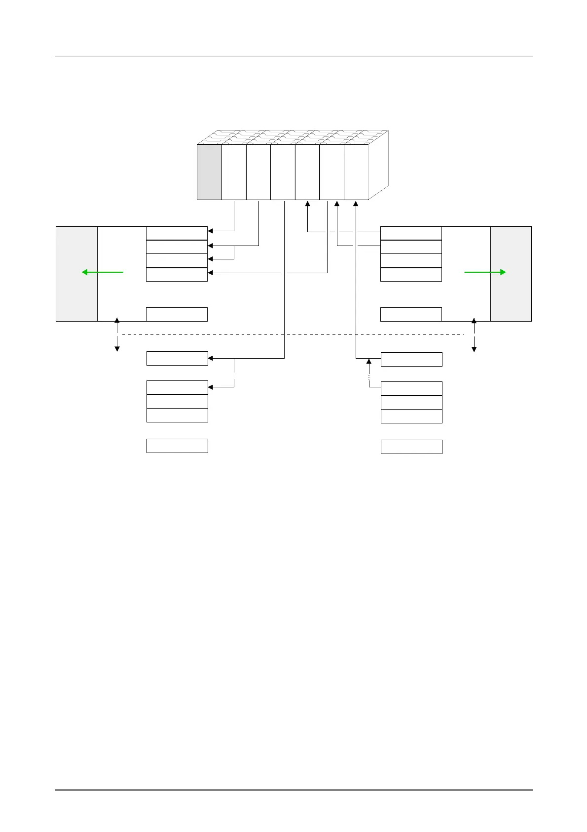
The following figure illustrates the automatic allocation of addresses:
CPU 21x
Input byte 0
.
.
.
128
.
.
.
135
136
137
.
.
.
1023
rel. Addr.
Peripheral area
DI 8xDC24V
DI 16xDC24V
AI 4x12Bit
DO 8xDC24V
DIO 8xDC24V
AO 4x12Bit
analog
digital
.
.
.
.
.
.
.
.
.
Input byte 1
Input byte 2
Input byte 3
Input byte 127
Input byte 0
Input byte 7
Input byte 8
Input byte 9
Input byte 1023
Output byte 0
.
.
.
Peripheral area rel. Addr
.
.
.
.
.
.
Output byte 1
Output byte 2
Output byte 3
Output byte 127
Output byte 0
Output byte 7
Output byte 8
Output byte 9
Output byte 1023
0
1
2
3
.
.
.
127
128
.
.
.
135
136
137
.
.
.
1023
analog
digital
PIQ
0
1
2
3
.
.
.
127
PII
Slot: 1 2 3 4 5 6
You may change the allocated addresses at any time by means of the
Siemens SIMATIC manager. In this way you may also change the addres-
ses of analog modules to the range covered by the process image
(0 ... 127) and address digital modules above 127.
The following pages describe the required preparations and the procedure
for this type of configuration.
Example for auto-
matic address
allocation
Modifying allocated
addresses by
configuration