9
Operating instructions
108
Counterweight installation
North America, International and Korea
Counterweight removal
1 Position the machine on flat, firm and level ground, free from
any obstructions or interference.
2 Keep the service position.
3 Pullthe safety locking lever securely. See
Safety locking sys-
tem on page 81.
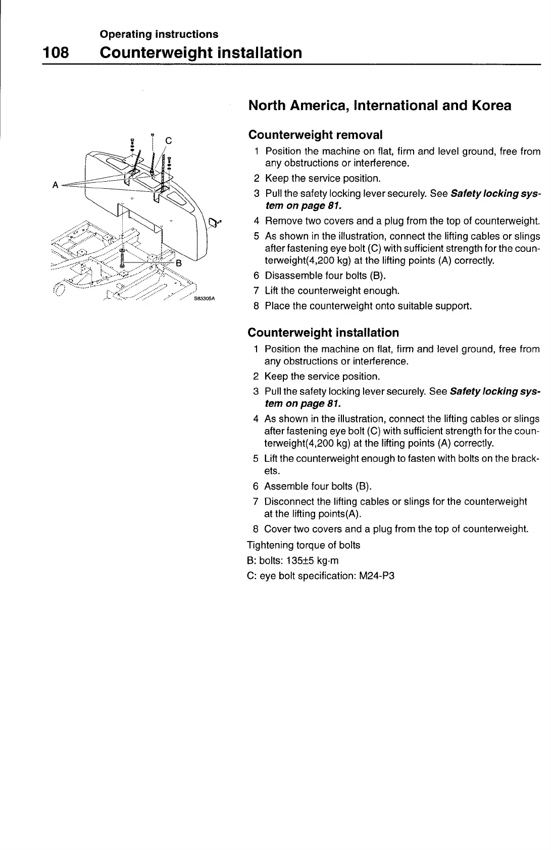
4 Remove two covers and a plug from the top of counterweight.
5 As shown in the illustration, connect the lifting cables or slings
after fastening eye bolt (C) with sufficient strength for the coun-
terweight(4,200 kg) at the lifting points (A) correctly.
6 Disassemble four bolts (B).
7 Lift the counterweight enough.
8 Place the counterweight onto suitable support.
Counterweight installation
1 Position the machine on flat, firm and level ground, free from
any obstructions or interference.
2 Keep the service position.
3 Pullthe safety locking lever securely. See
Safety locking sys-
tem on page 81.
4 As shown in the illustration, connect the lifting cables or slings
after fastening eye bolt (C) with sufficient strength for the coun-
terweight(4,200 kg) at the lifting points (A) correctly.
5 Lift the counterweight enough to fasten with bolts on the brack-
ets.
6 Assemble four bolts (B).
7 Disconnect the lifting cables or slings for the counterweight
at the lifting points(A).
8 Cover two covers and a plug from the top of counterweight.
Tightening torque of bolts
B:
bolts: 135±5 kg.m
C:
eye bolt specification: M24-P3