Service and maintenance
Electrical system
181
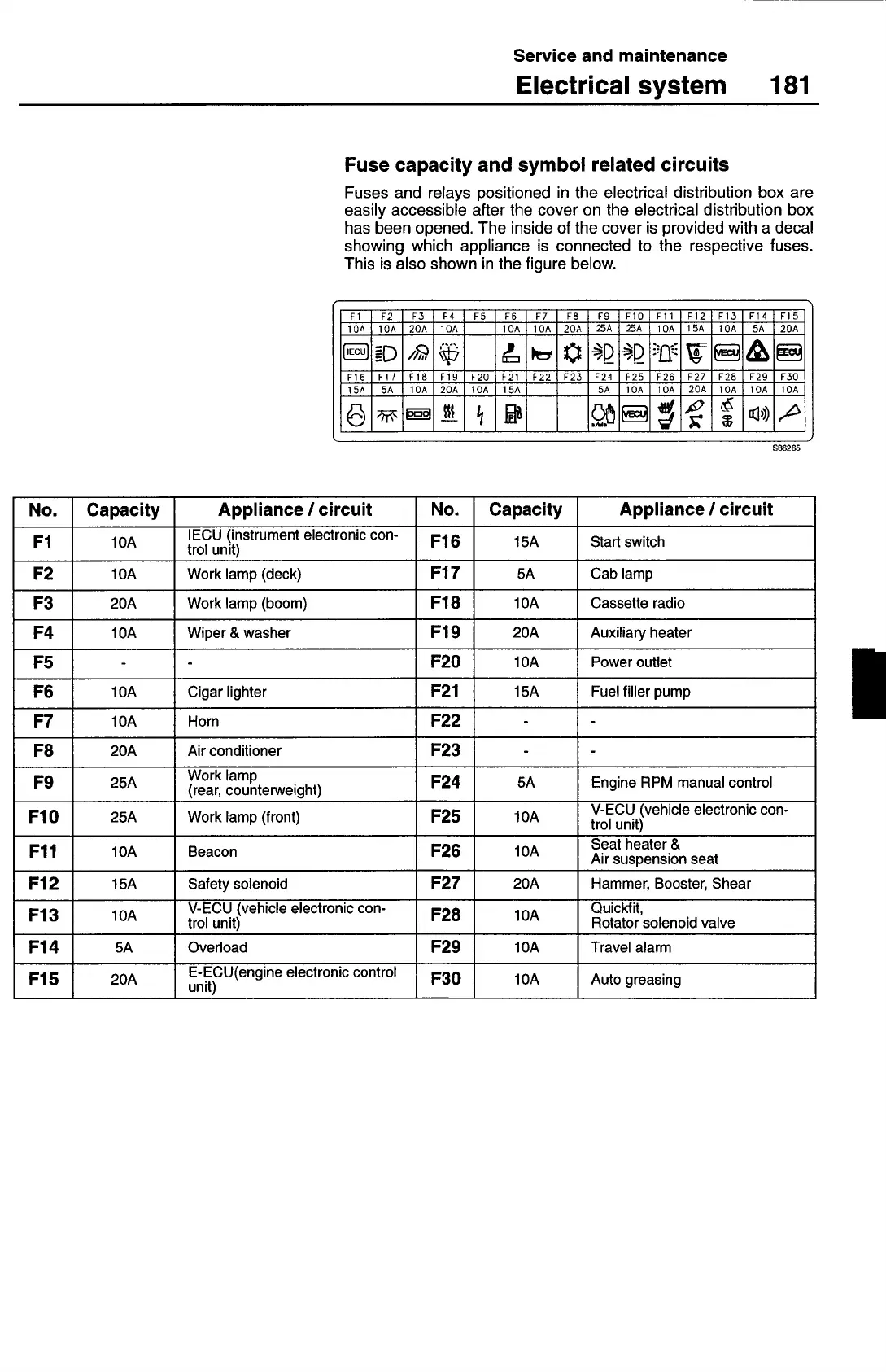
Fuse capacity and symbol related circuits
Fuses and relays positioned in the electrical distribution box are
easily accessible after the cover on the electrical distribution box
has been opened. The inside of the cover is provided with a decal
showing which appliance is connected to the respective fuses.
This is also shown in the figure below.
Fl
F2
13
14
ES
F6
17
F8
19
FIO
FI1
112
113
114
115
1OA
1OA
20A
1OA
bA
1OA
20A
A A
bA
iSA
1OA
5A
20A
116
Fbi
118
FlY
F20
F21
F22
123
F24
F25
126
F27
F28
129
F30
iSA
5A
1OA
20A
1OA
15A
5A
1OA
1OA
206
bOA
bOA
1OA
S86265
No.
Capacity
Appliance
I
circuit
No.
Capacity
Appliance
I
circuit
Fl
IOA
IECU (instrument electronic con-
trol unit)
F16
15A
Stan switch
F2
1OA
Work lamp (deck)
F17
5A
Cab lamp
F3
20A
Work lamp (boom)
F18
1OA
Cassette radio
F4
1OA
Wiper & washer
F19
20A
Auxiliary heater
F5
-
-
F20
1OA
Power outlet
F6
1OA
Cigar lighter
F21
15A
Fuel filler pump
F7
bA
Horn
F22
- -
F8
20A
Air conditioner
F23
-
-
F9
25A
Work lamp
(rear, counterweight)
F24
5A
Engine RPM manual control
F1O
25A
Work lamp (front)
F25
bOA
V-ECU (vehicle electronic con-
trol unit)
Fil
1OA
Beacon
F26
WA
Seat heater &
Air suspension seat
F12
15A
Safety solenoid
F27
20A
Hammer, Booster, Shear
Fl 3
1OA
V-ECU (vehicle electronic con-
trol unit)
F28
1OA
Quickf it,
Rotator solenoid valve
Fl4
5A
Overload
F29
1OA
Travel alarm
Fl 5
20A
E-ECU(engine electronic control
unit)
F30
1OA
Auto greasing