Operating instructions
Hydraulic quickfit (s1) (option) 87
VOE 2134355130
Hydraulic quickfit (s1) (option)
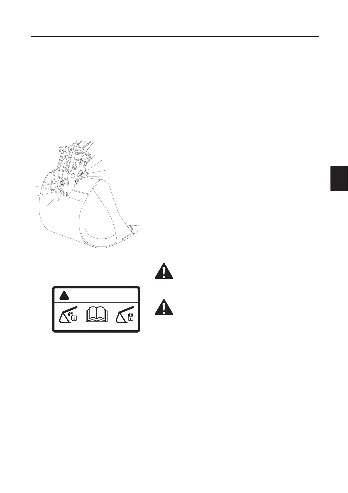
The quickfit consists of a flat plate assembly which is fitted to the
arm end and bucket link. There are two hooks (F) on the plate, for
the front pins (B) on the bucket.
There is a lifting hook (C) on the quickfit. With the bucket removed,
the permitted load increases and the operator’s field of vision is im-
proved.
The quickfit is equipped with a double-acting hydraulic cylinder.
The quickfit locking wedge (D) is fitted to its piston rod. Servo pres-
sure acts on the piston of the lock cylinder, locking the bucket in
place against rear hook (E). This means that the lock wedge ad-
justs itself and provides gap-free locking.
When lock wedge (D) is released, the servo pressure is transferred
to the piston rod side. If necessary, the release pressure can be in-
creased by loading the bucket cylinder in its end position.
There is a red indicator pin (A) on the left side of the quickfit, which
is pulled in when the locking wedge is in the locked position and
pushed out when the locking wedge is released.
A: Red indicator pin
B: Bucket shafts
C: Lifting hook
D: Locking wedge
E: Bucket rear hook
F: Hooks for gripping attachment
WARNING!
When attaching or disconnecting a quickfit, make sure
nobody enters the working area.
WARNING!
If the ce ntral warning lamp and quickfit indica tor light up
the quickfit is open, and if the bucket is still in the quickfit,
the arm must not be manoeuvred. If this should be
necessary anyway, use the greatest possible care, since
the bucket can s udden ly loosen and fall off.
Shut-off valve s must not be installed on the pipes leading
to the quickfit hydraulic cylinder. If the pressure in the
cylinder drops , the bucket may fall off.
S82330
D
A
E
C
B
F
WARNING
!
S80471