24
(1)(1)
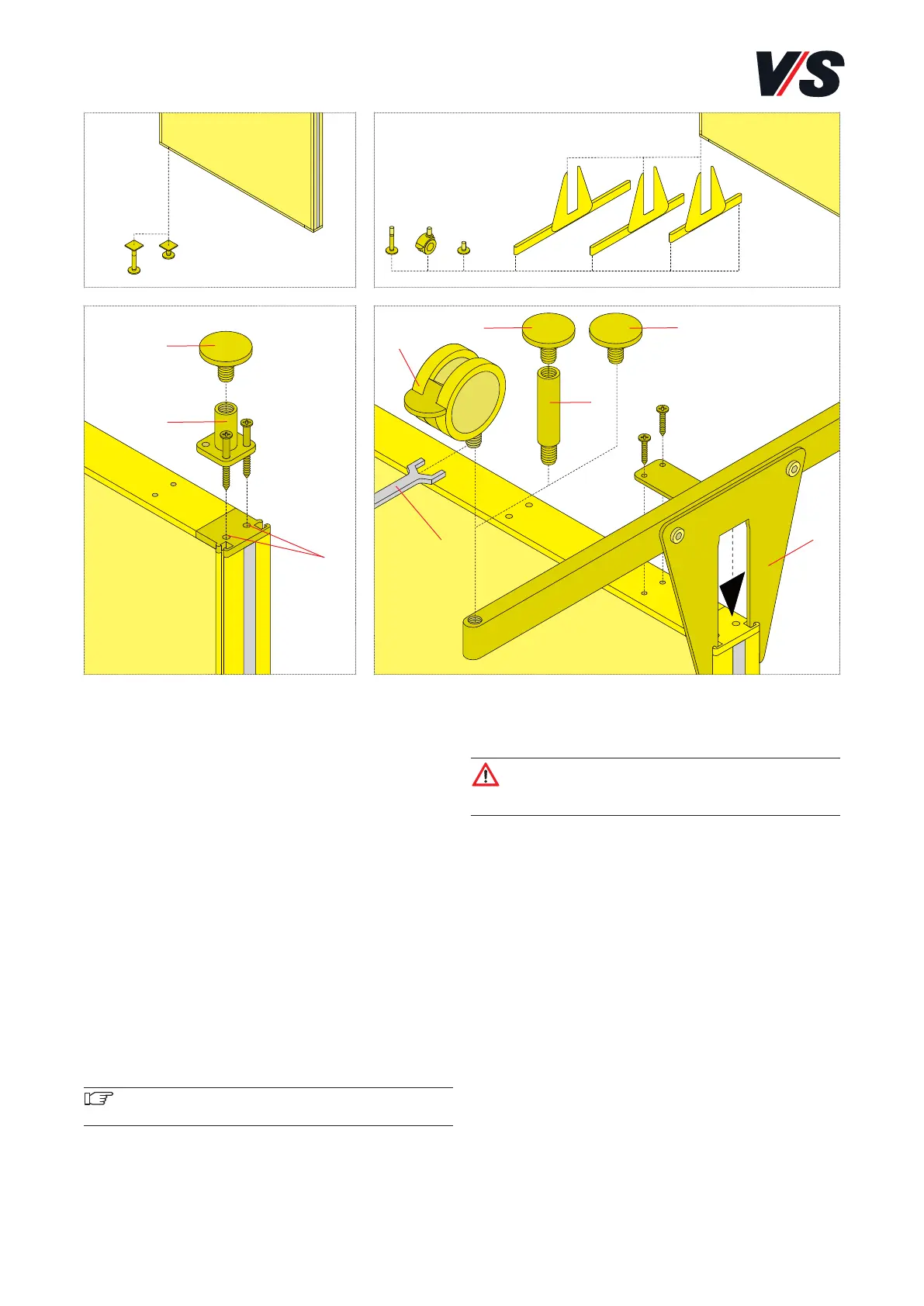
(1)
(2)
(3)
(7)
(6)
(5)
(4)
Align the gusset plate (6) and secure in the aluminium
profile with 2 4.8 x 19 pan-head tapping screws.
Caution! The long stabiliser side may pose a tripping
hazard! Eliminate this hazard by engaging a storage
board at a height of 1 to 1.3 m.
Mounting glide elements on stabiliser: Screw glide element
(1) into the female thread of the stabiliser, see Stand foot.
Mounting castors on stabiliser: Screw castor (4) into the
female thread of the stabiliser, see Stand foot. Mounting
spacer on stabiliser: (to obtain the castor height) Screw
spacer (5) with glide element (1) into the female thread of
the stabiliser, see Stand foot.
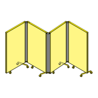
5. Functional screen. Mounting stand
foot and stabiliser.
Assembling functional screen with stand feet. Models
05430-05443.
Mounting stand foot: Secure base assembly (2) with 2 4.8 x
60 pan-head tapping screws in screw channel (3) of the
clamping rail. Screw glide elements (1) back into the base
assembly.
Or: Screw castor (4) into the female thread of base assem-
bly (2) with 12 WAF (7).
Or: (to obtain the same height as with castors) Screw spacer
(5) into the female thread of base assembly (2). Screw glide
element (1) into the female thread of spacer (5).
Assembling functional screen with stabiliser. Models
05400-05413, 05415-05428.
Long stabilizer on one side = Maximum total load of 20 kg
on long stabilizer side, no loading of the functional screen
permitted on the short stabilizer side.
Important! This is a tight fit because the gusset plate
is prestressed.