OM 25-3503 us – Edition 4.1 * 2503_3503b330.fm 3-61
Operation
1 Read and follow all instructions indicated before.
2 Fit an empty standard bucket and lock it safely.
3 Remove all dirt from the machine.
4 Park the machine on firm, level and horizontal ground.
5 Tilt in the standard bucket and lower it to transport position.
6 Fully raise the boom.
7 Pull the stick toward the machine.
8 Raise the stabilizer blade as far as it will go.
9 Set the slewing stabilizer blade (option 3503) straight.
10 Position the boom straight ahead at the center of the machine.
11 Stop the engine.
12 Operate the control lever repeatedly to release the pressure in the hydraulic system.
13 Raise the control lever base.
14 Remove the starting key and carry it with you.
15 Remove all loose objects from inside the machine.
16 Leave the cabin, close and lock all doors, windows and covers.
17 Install suitable slings at the points provided for lifting the machine.
18 Slowly raise the machine until there is no more contact with the ground.
19 Wait until the machine does not swing any more and is completely steady.
20 If the balance, and the condition and position of the slings is correct, slowly raise
the machine to the required height and load it.
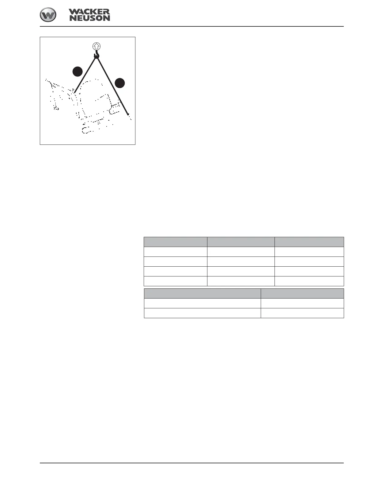
Mandatory lengths L1 and L2 of the lifting gear:
Fig. 152: Craning operation (symbolic representation)
L1
L2
Excavator Length Dimension
2503 L1 2240 mm (88 in)
2503 L2 3670 mm (12'-0'')
3503 L1 2270 mm (89 in)
3503 L2 4000 mm (13'-1'')
Authorized loads Force
Boom lifting eye 40 kN (8992 lbf)
Stabilizer blade lifting eye 40 kN (8992 lbf)