G 150 / 180 / 240 Operation
wc_tx000867gb.fm 25
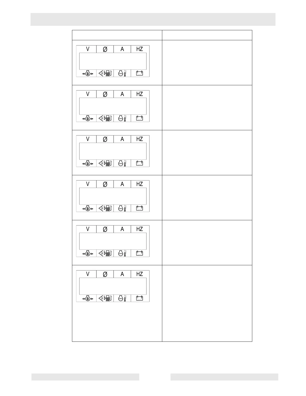
At this point in the sequence, the ECM
displays running values.
The ECM displays this screen to let
the operator know that the engine
protection system has been enabled.
The ECM displays the AC
configuration as determined by the
position of the voltage selector switch
(VSS).
The ECM displays this screen to let
the operator know that the alternator
protection system has been enabled.
The ECM displays the line-to-line
voltage. (This screen is shown for 3-
phase VSS positions only.)
At this point, the ECM displays the run
screen and the values for the main
generator variables: voltage, phase*
(leg), amperage, Hertz. The ECM will
also display the values for the main
engine variables: oil pressure, fuel
tank quantity, engine temperature, and
battery voltage.
*Note: The ECM display scrolls
through each phase (P1, P2, P3) if in
the 3-phase mode, or L1, L3, and L1 +
L3 if in the single-phase mode.
ECM Display Description
480 P2 0 60.0
71 75% 87 12.7
Eng Protection
Enabled
AC Configuration
Alt Protection
Enabled
Rated Volts L–L
480 P2 0 60.0
71 75% 87 12.7