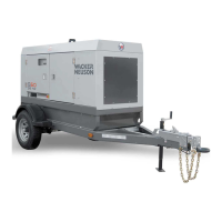
G 150 / 180 / 240 Schematics
wc_tx000879gb.fm 65
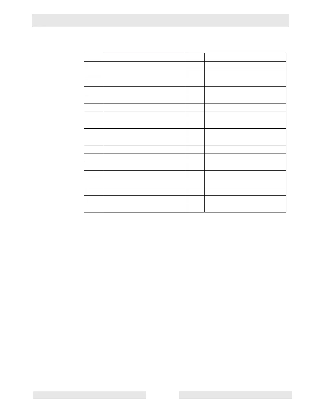
5.2 DC Schematic Components
Ref. Description Ref. Description
1 Electronic control board 19 Remote start
2 Engine outputs 20 Emergency stop switch
3 Engine sensor inputs 21 Toggle switch
4 Emergency stop 22 10A fuse
5 Cold crank delay 23 Main breaker
6 Remote start 24 Lug door safety switch
7 Fuel level 25 Mechanical lugs
8 Battery - 26 Relay (if equipped)
9 Battery + 27 Intake heater (if equipped)
10 Crank 28 Starter relay
11 Run / fuel 29 Starter
12 Remote annunciator 30 Alternator
13 21 position connector 31 12V battery
14 Start relay 32 Battery disconnect switch
15 Alternator / charge 33 John Deere engine ECU
16 B+ switched 34 Engine harness
17 Crank delay 35 Terminal block
18 Fuel level 36 Resistor (if equipped)