TECHNICAL CHARACTERISTCS
TR05A140.B1107
13
3.6 Control panel and display
The appliance MUST be supplied with a permanent live in order for the boiler’s protective functions to
operate. These functions include frost protection, post-ventilation, pump overrun and pump & 3-way
valve inactivity protection. On first connection to the power supply, the appliance must be switched on
using the ON/OFF button on the control panel to activate all of the above protective features. The
appliance can then be switched off but the protective features will remain active.
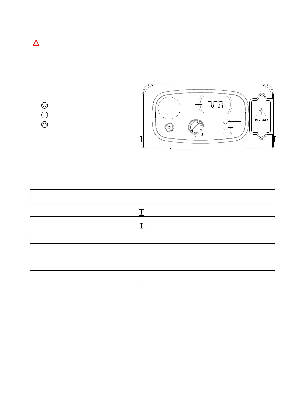
3.6.1 Layout
1. ON/OFF button
2. CH Control knob
3. DISPLAY button
4.
SERVICE button
5. MODE button
6. Mains supply terminal board
7. Digital LCD display
8. Programmer location (N/A)
3.6.2 Boiler operation
Mode / Control Input Display will show:
Boiler switched off
OFF
Press ON/OFF button (to switch the boiler on)
Primary circuit temperature in ºC
Icon – lit when appliance switched on
CH controls call for heat
Primary circuit temperature in ºC
Icon – flashes whilst CH mode is active
CH Control knob turned
CH set point temperature in ºC – displayed for 3 seconds
SERVICE button pressed & held for 7 seconds
Function Code 07 – flashes whilst activated
(see Section 3.6.3)
Boiler protection function activated
(automatically)
Function Code 08 – flashes whilst activated
(see Section 3.6.3)
Boiler locked out
Error Code – flashes whilst locked out
(see Section 6.8.1)
Table 3: Control panel display
Figure 6: Control Panel
1 2
ON / OFF
3 4 5 6
78