MAINTENANCE INSTRUCTIONS
TR05A140.B1107
49
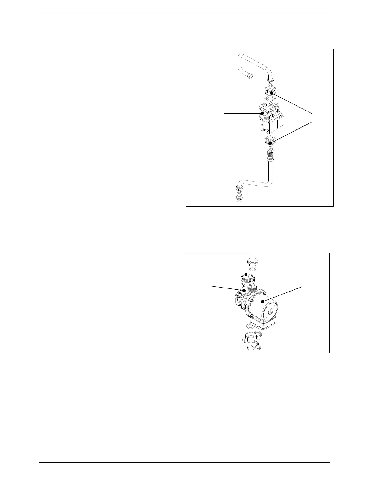
6.6.5 Gas valve
• Isolate the electricity, water and gas supplies to the
appliance;
• Disconnect and remove the gas pipe connecting the
gas valve to the venturi;
• Disconnect the gas feed pipe and valve ring nut at
the bottom of the room sealed chamber;
• Remove the couplings of the existing valve and fit to
the new valve using new cork gaskets;
• Replace the gas valve and reassemble the
components following the above procedure in
reverse order, replacing all the gas seals;
• Switch on the gas supply and check for any gas
leaks using soapy water or leak detector spray;
• Switch on the electricity and water supplies, switch
on and fire the appliance and repeat the checks for
leaks.
6.6.6 Circulating pump motor body
• Isolate the electricity, water and gas supplies to the
appliance;
• Drain the central heating circuit of the boiler (see
Section 6.4);
• Use a 5 mm Allen key to unscrew the four screws
securing the motor body to the impeller body;
• Remove the motor body and check the condition of
the gasket. Replace if necessary;
• Replace the pump motor body and reassemble the
components following the above procedure in
reverse order;
• Switch on the electricity, water and gas supplies;
• Refill the system (see Sections 5.2) and check for
any leaks.
Figure 43: Gas valve
Gas valve
Couplings
Figure 44: Circulating pump
Pump motor body
Pump impeller body