MAINTENANCE INSTRUCTIONS
TR05A140.B1107
51
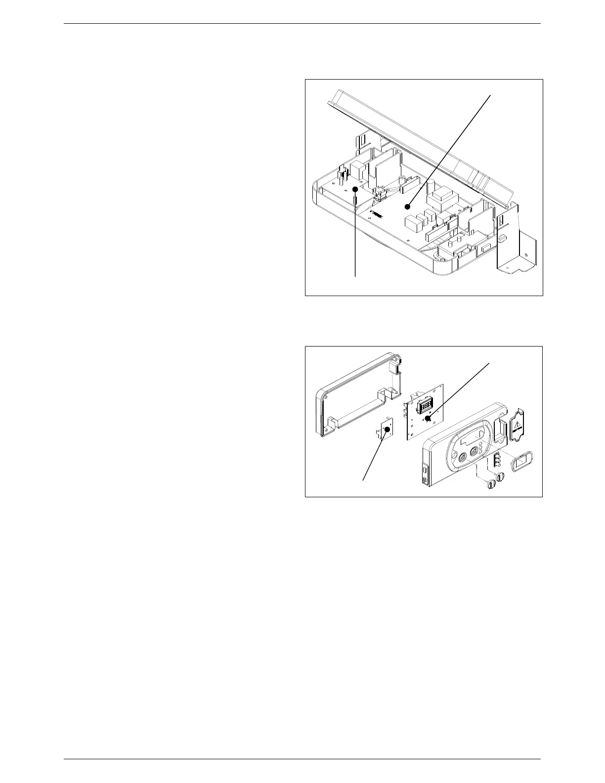
6.6.9 Modulation circuit board
• Isolate the electricity, water and gas supplies to the
appliance;
• Access the control panel (see Section 6.3);
• Disconnect all the connectors, remove the control
knobs from the front of the panel, unscrew the fixing
screws and remove the modulation circuit board;
• Replace the circuit board and reassemble the
components following the above procedure in
reverse order;
• Switch on the electricity, water and gas supplies;
• Program the boiler control parameters following the
instructions in Sections 5.7.
6.6.10 Electric fan circuit board
• Isolate the electricity, water and gas supplies to the
appliance;
• Access the control panel (see Section 6.3);
• Disconnect the two connectors from the fan circuit
board, unscrew the two fixing screws and remove the
board;
• Replace the circuit board and reassemble the
components following the above procedure in
reverse order.
6.6.11 Primary heat exchanger replacement
• Isolate the electricity, water and gas supplies to the appliance;
• Drain the central heating circuit of the boiler (see Section 6.4);
• Remove and dismantle the entire burner unit (see Section 6.6.1);
• Remove the gas valve (see Section 6.6.5);
• Remove the condensate drainpipe;
• Remove the flow and return pipe work;
• Remove the support brackets and pull out the heat exchanger;
• Remove the sensors and pipes from the old exchanger and fit them to the new one;
• Replace the heat exchanger and reassemble the components following the above procedure in reverse order;
• Switch on the electricity, water and gas supplies;
• Refill the system (see Sections 5.2) and check for any leaks;
• Fire the boiler and check for any flue gas leaks.
Electric fan circuit board
Modulation circuit board
Electric fan circuit board
Modulation circuit board
Figure 50: Circuit boards