MAINTENANCE INSTRUCTIONS
TR05A140.B1107
47
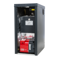
6.6.1 Primary heat exchanger and burner unit
• Isolate the electricity, water and gas supplies to
the appliance;
• Disconnect the electrical connections of the
electric fan;
• Disconnect and remove the pipe linking the gas
valve to the venturi;
• Disconnect and remove the gas feed pipe from
the gas valve;
• Unplug the ignition and ionisation electrode
wires from the ignition control unit;
• Unscrew the ring nut at the bottom of the room
sealed chamber and remove the gas valve;
• Unscrew the nuts securing the burner unit
(consisting of a fan, manifold and burner) to the
primary heat exchanger;
• Remove the burner unit, taking particular care
not to remove the ceramic fibre board from the
end of the heat exchanger;
• Check that the burner is not affected by
deposits, scaling or excessive oxidation. Check
that all the holes in the burner are free;
• Clean the electrodes carefully without altering
their positions with respect to the burner;
• Clean the burner cylinder using a non-metal
brush and without damaging the ceramic fibre;
• Check the integrity of the seal on the cover of
the burner;
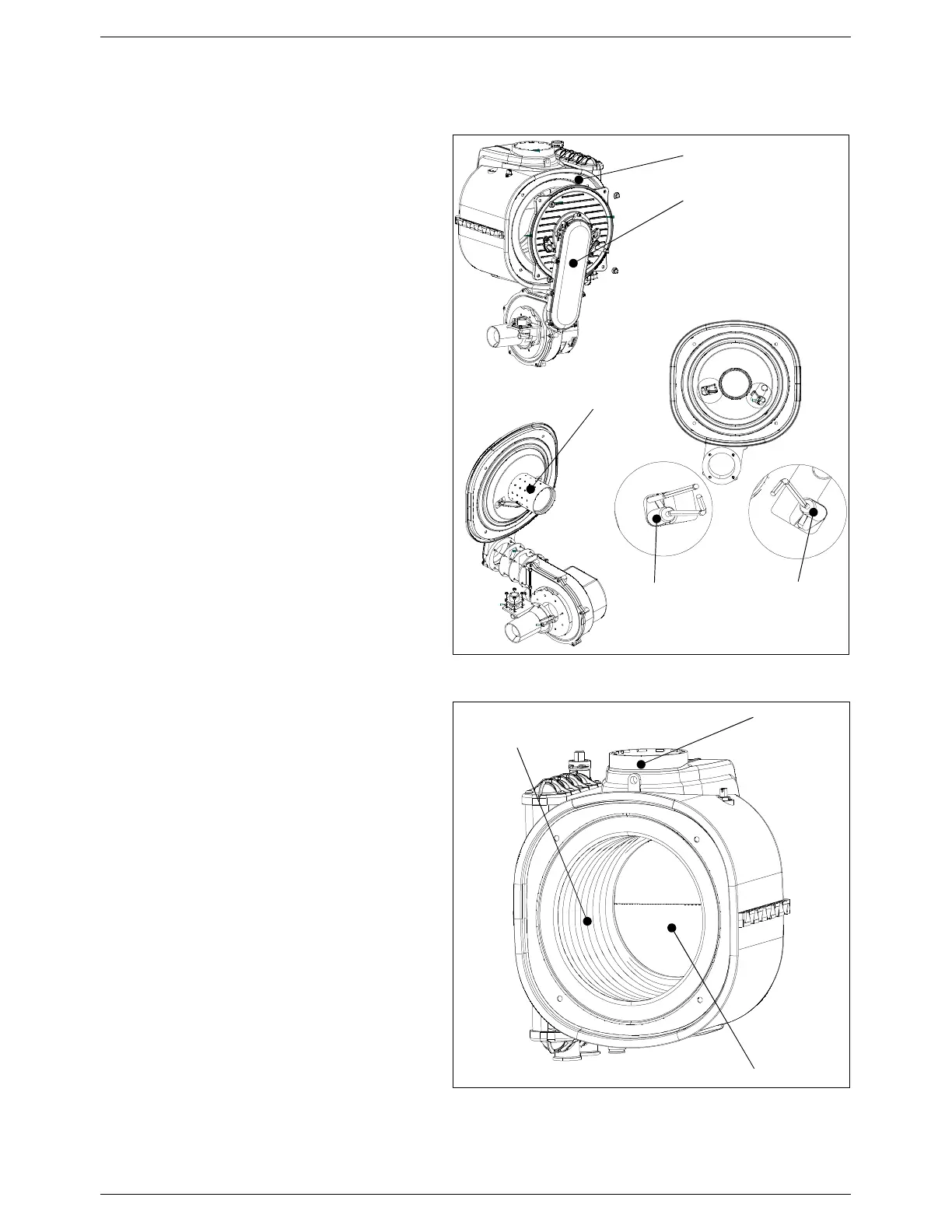
• Clean the heat exchanger using a suitable
detergent for stainless steel, distributing the
product on the spirals of the exchanger using a
brush. Do not wet the ceramic fibre board. Wait
a few minutes then remove the deposits using a
non-metal brush. Remove the residues under
running water;
• Remove the condensate drain pipe and clean
under running water;
• Unscrew the joint to the condensate trap,
remove the trap and wash under running water;
• With the cleaning completed, re-assemble the
components following the above procedure in
reverse order;
• Finally, check the boiler to make sure that all
gas and exhaust joints are tight.
B
A
Figure 38: Primary heat exchanger and burner unit
Primary heat exchanger
Premix burner unit
Burner
Ignition
electrode
Ionisation
electrode
Figure 39: Primary heat exchanger
Ceramic fibre
Stainless steel
exchanger coils
Flue manifold