MAINTENANCE INSTRUCTIONS
TR05A140.B1107
48
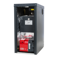
6.6.2 Ignition and ionisation electrodes
• Isolate the electricity, water and gas supplies to the
appliance;
• Unplug the electrode wires;
• Slacken the fixing screws;
• Remove the electrodes. When refitting the
electrodes, check that the seals are not damaged
and replace if necessary;
• Reconnect the wires and reassemble the
components following the above procedure in
reverse order;
• Switch on the power supply and restart the
appliance;
If the boiler does not restart, check the
positions of the electrodes. The ignition
electrode should be positioned with a 10mm
gap between it and the burner. The ionisation
electrode must not be touching the burner
surface.
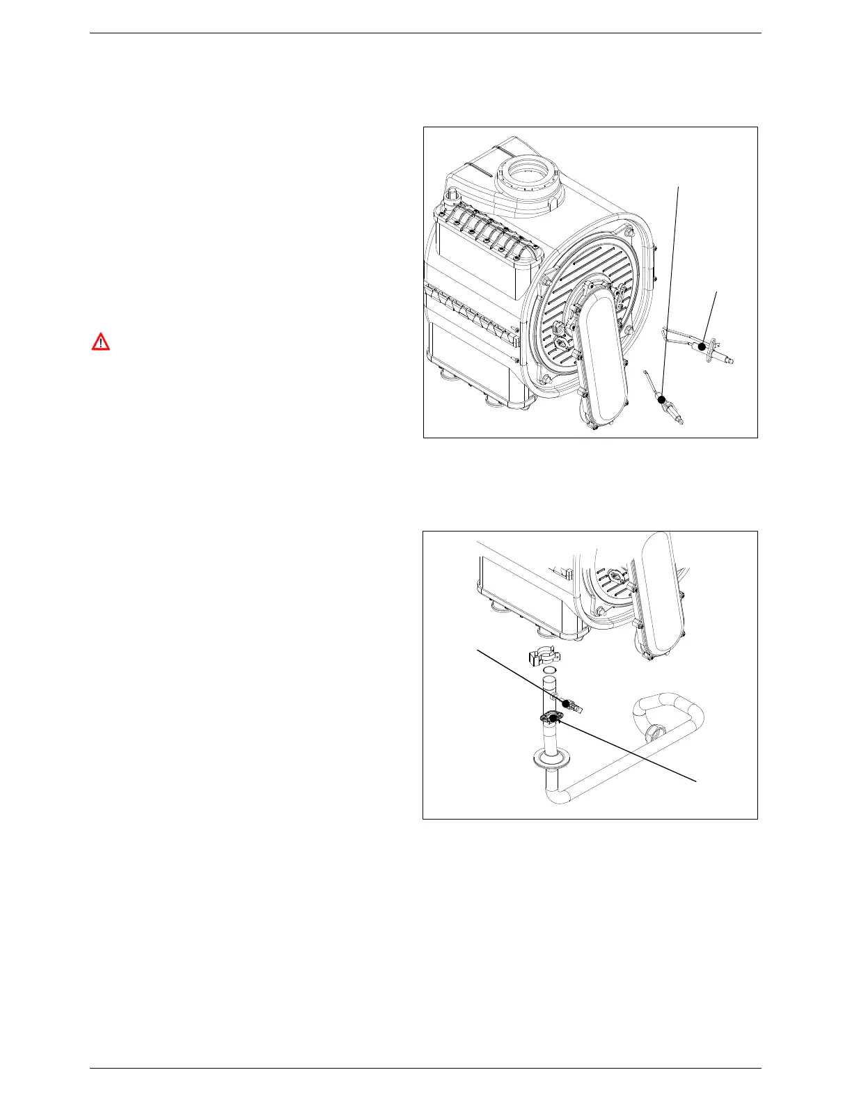
6.6.3 Safety thermostat
• Isolate the electricity, water and gas supplies to the
appliance;
• Disconnect the connecting wire;
• Unscrew the fixing screws and remove the
thermostat;
• Replace the thermostat and re-assemble the
components following the above procedure in
reverse order;
6.6.4 Heating sensor
• Isolate the electricity, water and gas supplies to the
appliance;
• Unplug the connecting wires;
• Replace the sensor (expecting some water loss)
and reconnect the wires;
• Refill the system (see Sections 5.2) and check for
any leaks.
Ignition
electrode
Ionisation
electrode
Figure 41: Ignition and ionisation electrodes
Safety thermostat
Heating sensor
: Safety thermostat and heating sensor