MAINTENANCE INSTRUCTIONS
TR05A140.B1107
50
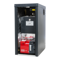
6.6.7 Electric fan
• Isolate the electricity, water and gas supplies to the
appliance;
• Remove and dismantle the entire burner unit (see
Section 6.6.1);
• Use an 8 mm spanner to unscrew the four nuts
securing the electric fan to the gas manifold and
then remove the electric fan, noting the positions of
the washer and diaphragm (see Figure 45);
• Remove the air intake duct, unscrew the two fixing
screws from the venturi and remove the electric fan,
paying particular attention not to damage the cork
gasket.
• Replace the electric fan and reassemble the
components following the above procedure in
reverse order.
• Switch on the electricity, water and gas supplies and
check the soundness of the joint by measuring the CO
2
levels;
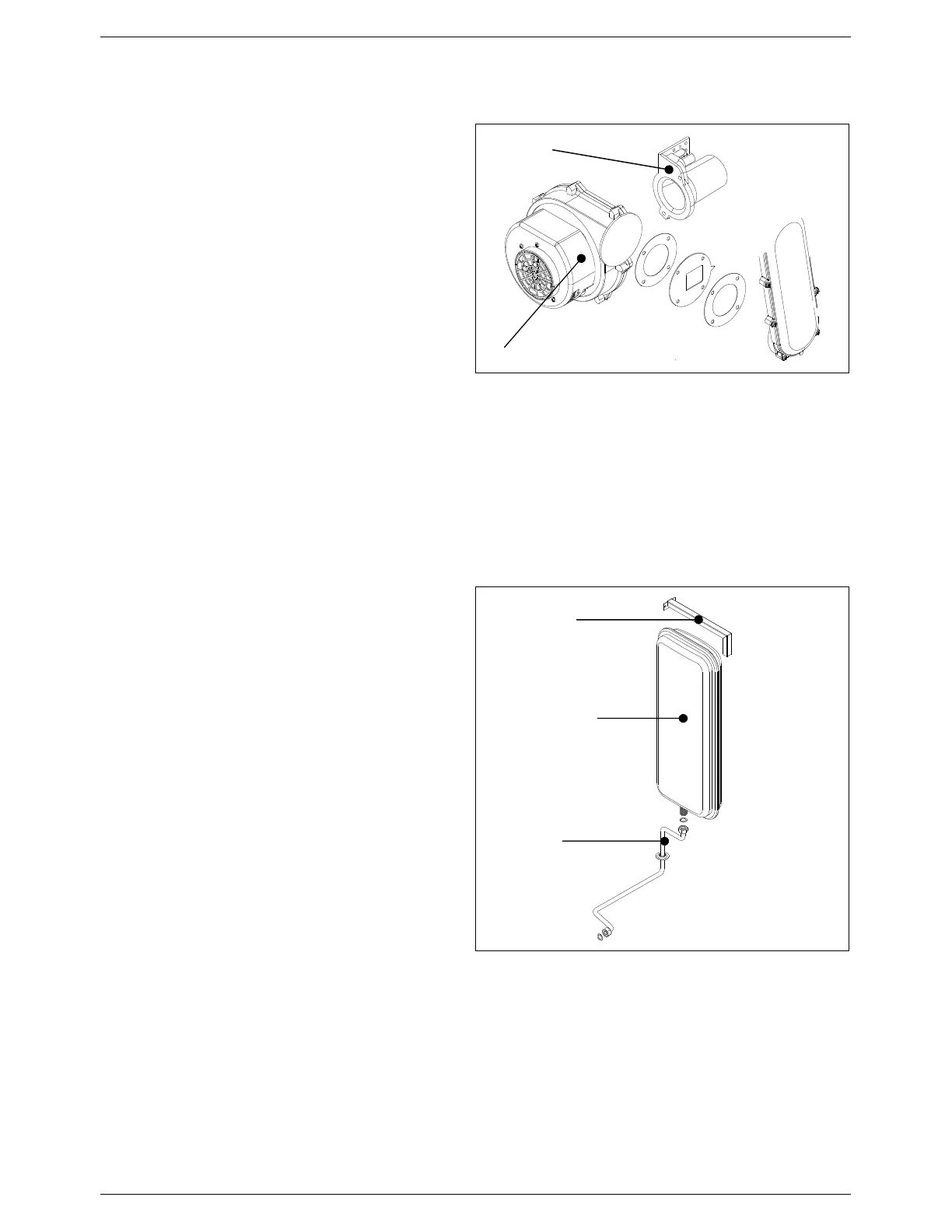
6.6.8 Expansion vessel
• Isolate the electricity, water and gas supplies to the
appliance;
• Drain the central heating circuit of the boiler (see
Section 6.4);
• Use a 19 mm spanner to unscrew the vessel pipe
coupling;
• Unscrew the fixing screws and remove the upper
mounting bracket. Remove the expansion vessel
from the front of the boiler;
• Replace the expansion vessel and reassemble the
components following the above procedure in
reverse order;
• Switch on the electricity, water and gas supplies;
• Refill the system (see Sections 5.2) and check for
any leaks.
Venturi
Fan
Figure 45: Fan assembly
Fixing bracket
Expansion vessel
Vessel pipe
Figure 46: Expansion vessel