Preparing the column compartments 69
Tip: Use a pen to coil any excess tubing on any of the connections.
5. When all valve connections are made, rotate the valve’s lock ring
counterclockwise, to the 12 o’clock position.
6. Push the switching-valve assembly inward until it stops.
7. Plug all unused ports on the inlet and outlet switching valves using pin
plugs.
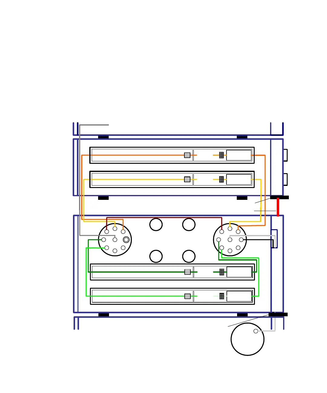
Four-column configuration, with inlet switching-valve on the
right-hand side:
Tubing
Router
3
4
1
2
B
3
4
5
WI
1
2
B
3
4
5
6
O
6
W
6
To detector
Column
position 1
Column
position 2
APH
APH
Column Manager-Aux
APH
APH
Column
position 3
Column
position 4
Drip tray
Column Manager
Sample Manager
Outlet
switching
valve
Inlet
switching
valve
Drip tube
Injector
Drip tray with
leak detector