NOTE:
Both Header Temp Sensor and Outdoor Sensor must be wired. See the Edge [i] Controller
Manual (OMM-0141, GF-213-B) for more information.
OPTION 4 Step 1: HEADER TEMP SENSOR WIRING – ANY BOILER
Using the Modbus Transmitter gives the plant the ability to use the Backup manager
feature. This allows any of the client units to become a Backup manager if the manager
unit is not communicating.
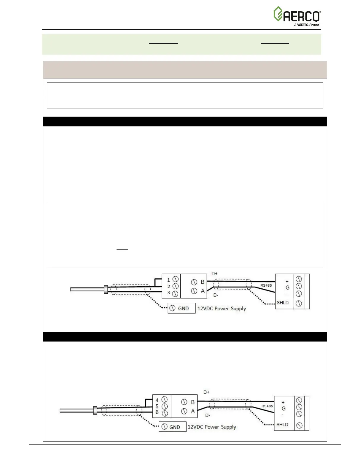
1. Connect the Modbus Transmitter terminal Pin B to the RS485+ terminal, and Pin A to the
RS485- terminal on the I/O Board of any Boiler unit, using shielded pair 18 - 22 AWG cable.
2. Connect the Header Temp Sensor (P/N 61040) to pins 2 and 3 of the Modbus Transmitter,
using shielded pair 18 - 22 AWG cable.
3. Install a jumper wire between pins 1 and 2 of the Modbus Transmitter.
NOTES:
• Polarity must be observed for the RS485 connections.
• Ground the shield to any SHLD terminal on the I/O Board.
• The Header Temp Sensor must be installed between 2 and 10 feet (0.61 and 3.1m)
downstream of the last boiler in the plant’s supply water header.
• There is no polarity to be observed. The ground for the shield is at the power supply
ground. The sensor end of the shield must be left free and ungrounded.
OPTION 4 Step 2: OUTDOOR SENSOR WIRING
1. If you have not already done so, complete step 1 of the instructions above to connect the
Modbus Transmitter to the I/O Board.
2. Connect the Outdoor Temp Sensor to Pins 5 and 6 of the Modbus Transmitter using a
shielded pair 18 - 22 AWG cable.
3. On the Modbus Transmitter, install a jumper wire between Pins 4 and 5.

 Loading...


