Benchmark with Edge [I]: Operation-Maintenance Manual
SECTION 4 – INITIAL START-UP
OMM-0145_D • GF-218 • 11/2/2020 Technical Support • (800) 526-0288 • Mon-Fri, 8 am - 5 pm EST Page 54 of 213
Figure 4-1f: Port Location for Combustion Calibration – BMK5000-6000
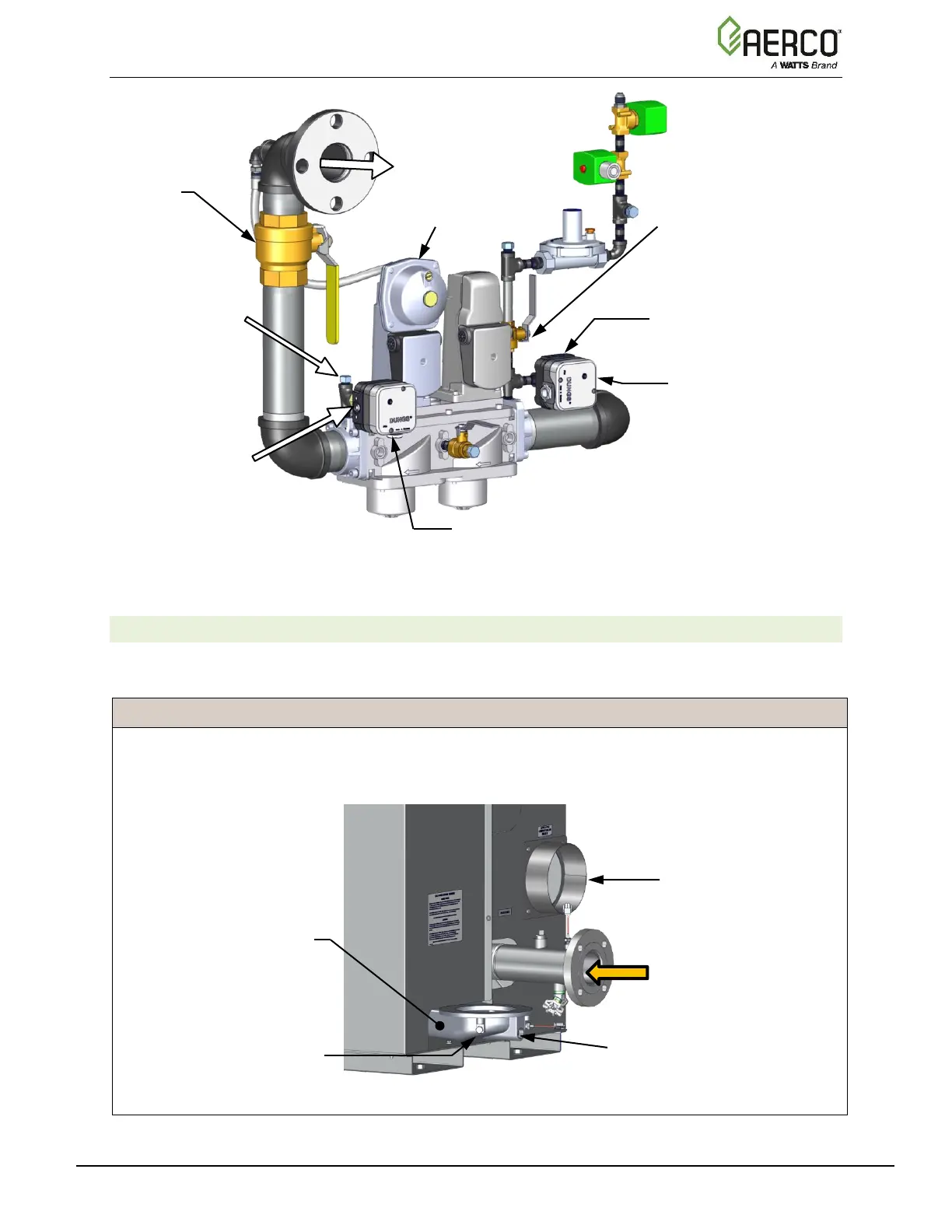
4.2.3 Accessing the Analyzer Probe Port
Benchmark units contain a 1/4” NPT port on the side of the exhaust manifold, as shown in
Figure 4-2. Prepare the port for the combustion analyzer probe as follows:
Analyzer Probe Port Access Instructions
1. Refer to Figure 4-2 and remove the 1/4” NPT plug from the exhaust manifold.
2. If necessary, adjust the stop on the combustion analyzer probe so it will extend mid-way into the flue
gas flow. DO NOT install the probe at this time.
Figure 4-2: Analyzer Probe Port Location – BMK750 & 1000 Shown
UPSTREAM LEAK
DETECTION BALL VALVE
GAS PORT
(Install manometer here for
downstream combustion
calibration reading)
DOWNSTREAM
SSOV WITH POC
SWITCH
GAS PORT
(Install manometer here for
upstream combustion calibration
reading)
Alternative location for
manometer if hose
barb is preferred

 Loading...


