NOTE:
Both Header Temp Sensor and 4-20ma Direct Drive must be wired. See the Edge [i]
Controller Manual (OMM-0141, GF-213-B) for more information.
OPTION 5 Step 1: HEADER TEMP SENSOR WIRING – BST MANAGER Unit
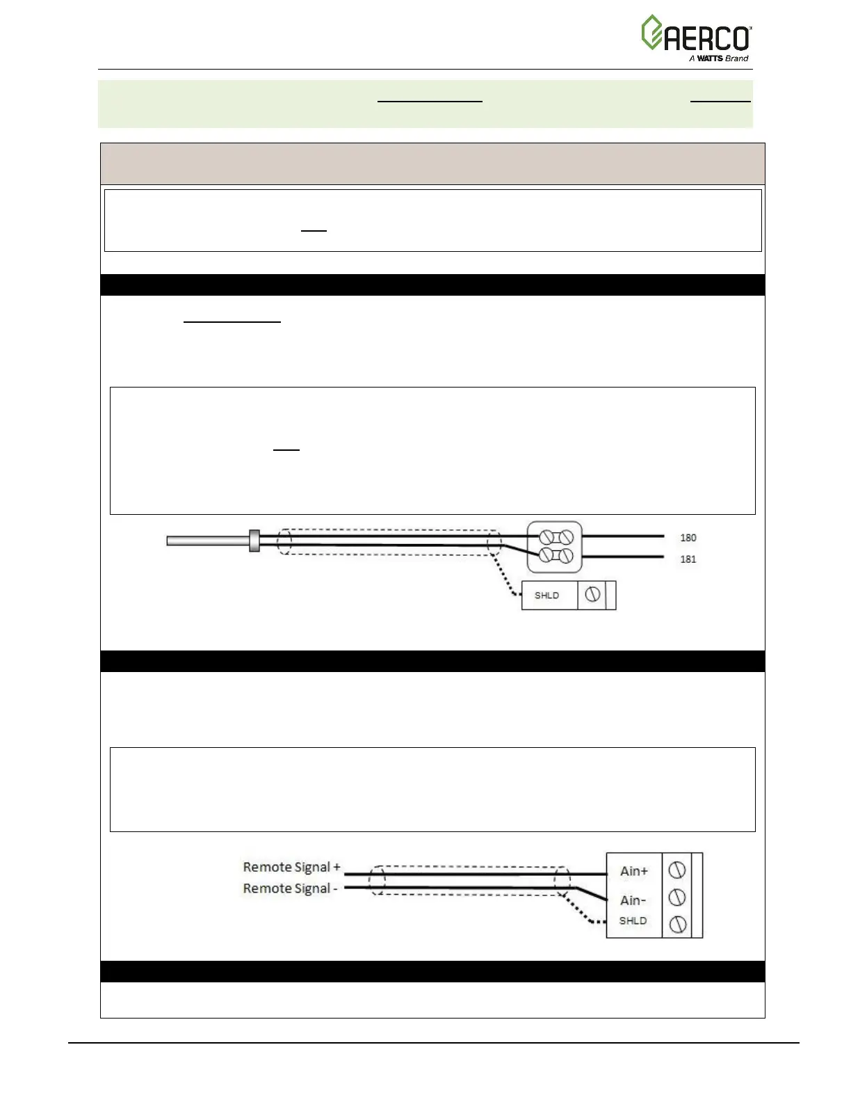
1. On the BST Manager unit, connect the Header Temp Sensor to the Feed Forward
(FFWD) terminals on the P-1 Harness via the terminal block labeled Header Temp sensor
on the I/O Board.
2. Ground the shield to any SHLD terminal on the I/O Board.
NOTES:
• The Header Temp Sensor must be installed between 2 and 10 feet (0.61 and 3.1m)
downstream of the last boiler in the plant’s supply water header.
• Shielded pair 18 - 22 AWG cable is recommended for Header Temp Sensor wiring.
There is no polarity to be observed. The ground for the shield is at the SHLD terminal on
the I/O Board. The sensor end of the shield must be left free and ungrounded.
OPTION 5 Step 2: DIRECT WIRED 0-20mA or 4-20mA WIRING – BST MANAGER Unit
1. Connect the 4-20mA or 0-20mA terminals from the Direct Drive source to the Ain+ and Ain-
terminals on the BST Manager’s I/O Board.
2. Connect the shield to any SHLD terminal on the I/O Board.
NOTES:
• Shielded pair 18 - 22 AWG cable is recommended for this connection. Polarity must be
observed.
• The ground for the shield is at the driver signal source.
OPTION 5 Step 3 – DAISY CHAIN WIRING BETWEEN BOILERS
1. Connect the boilers in a daisy chain, as shown below.

 Loading...


