Benchmark with Edge [I]: Operation-Maintenance Manual
SECTION 8 – MAINTENANCE
OMM-0145_D • GF-218 • 11/2/2020 Technical Support • (800) 526-0288 • Mon-Fri, 8 am - 5 pm EST Page 132 of 213
TABLE 8-2b: 24 Month Maintenance Kits
Parts Serviced/Replaced – Includes all 12 Month Parts
Burner & Blower gaskets, LWCO, air filter replacement
Burner & Blower gaskets, LWCO, air filter cleaner
Burner & Blower gaskets, LWCO, air filter replacement
Burner & Blower gaskets, LWCO, air filter cleaner
Burner & Blower gaskets, LWCO, air filter replacement
Burner gaskets, LWCO, air filter cleaner
Burner & Blower gaskets, LWCO, air filter replacement
Burner gaskets, LWCO, air filter cleaner
LWCO, air pump filter, Burner & Blower gaskets, air filter
LWCO, air pump filter, air filter
LWCO, air pump filter, Burner & Blower gaskets, air filter
cleaning kit
LWCO, air pump filter, air filter cleaning kit
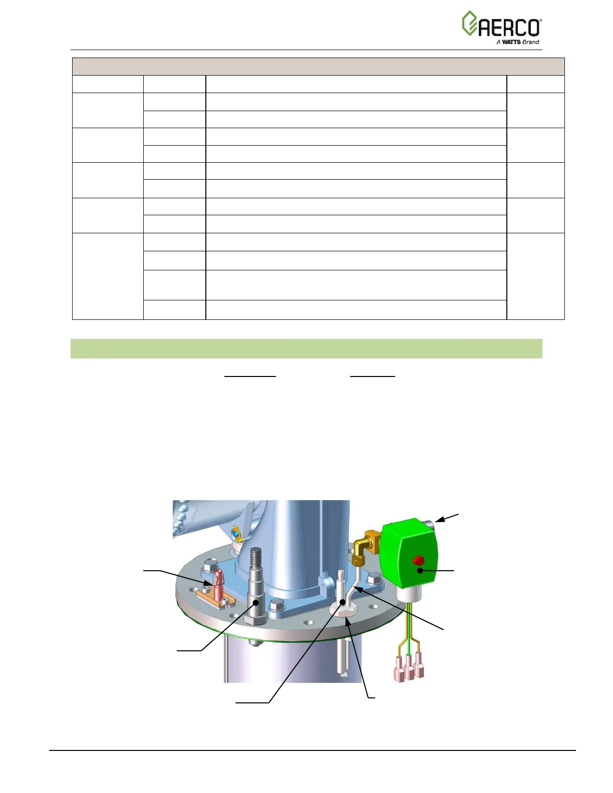
8.2 IGNITER-INJECTOR – BMK750 – 5000N
The ignitor-injector should be inspected annually and replaced at least every 24 months of
operation, sooner if there is evidence of substantial erosion or carbon build-up. Parts and
instructions are included in 12 Month Maintenance Kit P/N 58025-01 and all BMK750 – 5000N 24
Month Maintenance Kits.
The igniter-injector may be hot; therefore, care should be exercised to avoid burns. It is easier to
remove the igniter-injector from the unit after the unit has cooled to room temperature. To
inspect/replace the Igniter:
Note that during installation, use the number of indexing (clocking) washers necessary that,
when tight, the gas injection tube is positioned as shown in Figure 8-1d.
Figure 8-1a: Igniter-Injector & Flame Detector (BMK750/1000)
INDEXING (CLOCKING)
WASHERS (0-3 as required)

 Loading...


