NOTE:
Both Header Temp Sensor and Outdoor Sensor must be wired. See the Edge [i] Controller
Manual (OMM-0141, GF-213-B) for more information.
OPTION 6 Step 1: HEADER TEMP SENSOR WIRING – BST MANAGER Unit
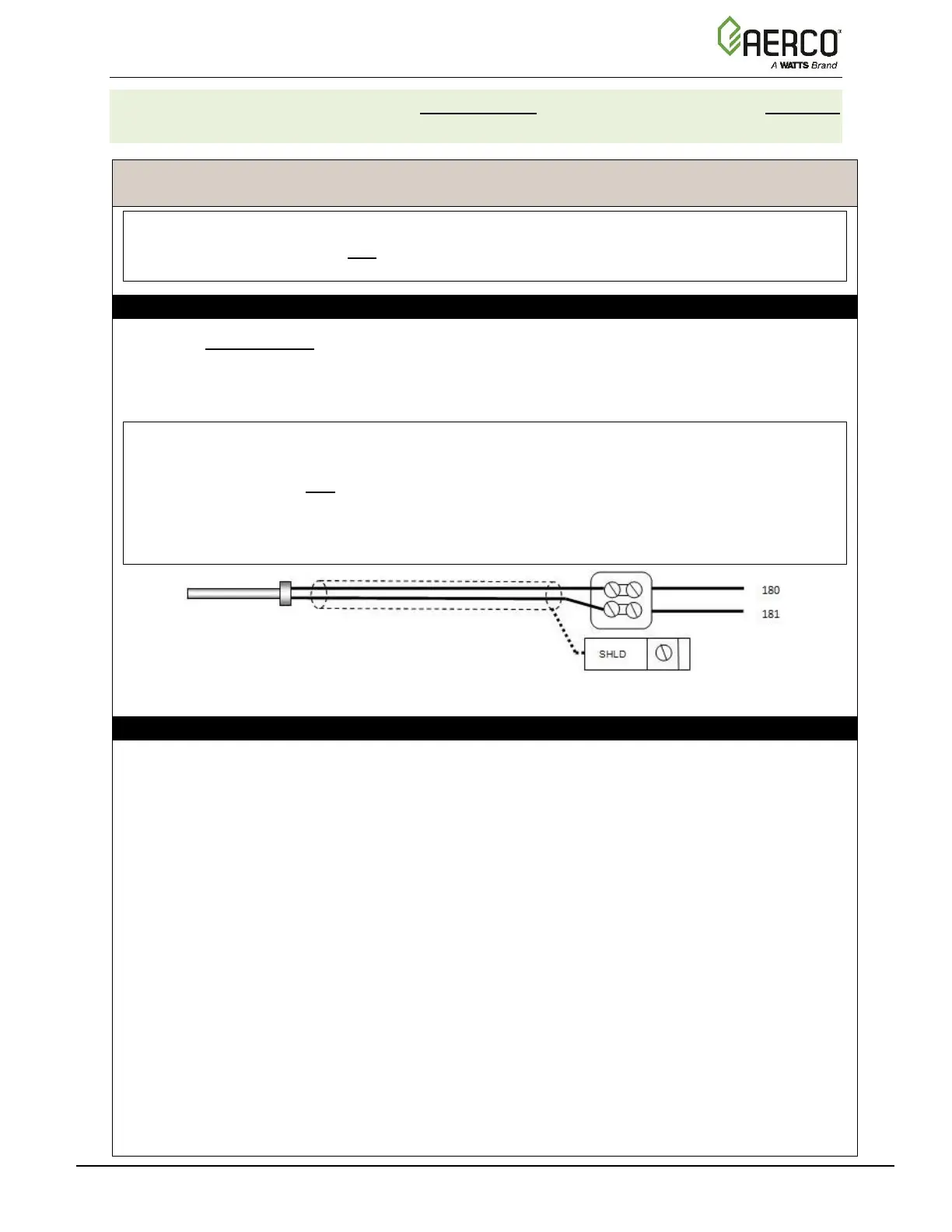
1. On the BST Manager unit, connect the Header Temp Sensor to the Feed Forward
(FFWD) terminals on the P-1 Harness via the terminal block labeled Header Temp sensor
on the I/O Board.
2. Ground the shield to any SHLD terminal on the I/O Board.
NOTES:
• The Header Temp Sensor must be installed between 2 and 10 feet (0.61 and 3.1m)
downstream of the last boiler in the plant’s supply water header.
• Shielded pair 18 - 22 AWG cable is recommended for Header Temp Sensor wiring.
There is no polarity to be observed. The ground for the shield is at the SHLD terminal on
the I/O Board. The sensor end of the shield must be left free and ungrounded.
OPTION 6 Step 2: CONFIGURE AND CONNECT SSD DEVICE (PROTONODE)
1. Connect the ProtoNode per the instructions in one of the ProtoNode FPC N34, FPC-N35
Manuals:
• For FPC-N34 (P/N 64129) or FPC-N35 (P/N 64130), see OMM-0107 (GF-150).
• For FPC-N34 (P/N 64168) or FPC-N35 (P/N 64169), see OMM-0150 (GF-150_B).
Continued on next page

 Loading...


