NOTE:
Both Header Temp Sensor and 4-20ma Direct Drive must be wired. See the Edge [i]
Controller Manual (OMM-0141, GF-213-B) for more information.
OPTION 7 Step 1: MODBUS HEADER TEMP SENSOR WIRING – ANY BOILER
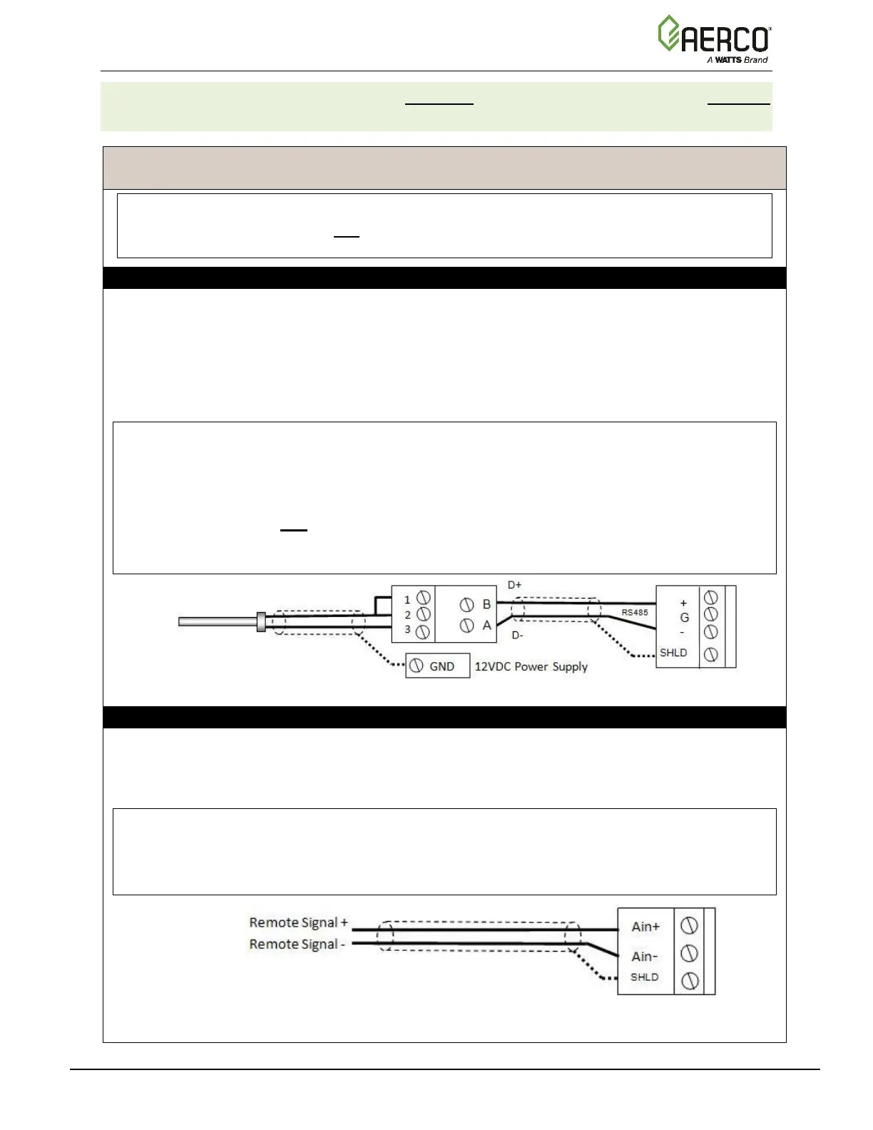
1. Connect the Modbus Transmitter terminal Pin B to the RS485+ terminal, and Pin A to the
RS485- terminal on the I/O Board of any Boiler unit, using shielded pair 18 - 22 AWG cable.
2. Connect the shield to any SHLD terminal on the I/O Board.
3. Connect the Header Temp Sensor to pins 2 and 3 of the Modbus Transmitter units using
Shielded pair 18 - 22 AWG cable.
4. On the Modbus Transmitter, install a jumper wire between pins 1 and 2.
NOTES:
• Polarity must be observed for the RS485 connections.
• Connect the shield to any SHLD terminal on the I/O Board.
• The Header Temp Sensor must be installed between 2 and 10 feet (0.61 and 3.1m)
downstream of the last boiler in the plant’s supply water header.
• There is no polarity to be observed. The ground for the shield is at the power supply
ground. The sensor end of the shield must be left free and ungrounded.
OPTION 7 Step 2: DIRECT WIRED 0-20mA or 4-20mA WIRING – BST MANAGER
1. Connect the 4-20mA or 0-20mA terminals from the Direct Drive source to the Ain+ and Ain-
terminals on the BST Manager.
2. Connect the shield to any SHLD terminal on the I/O Board.
NOTES:
• Shielded pair 18 - 22 AWG cable is recommended for this connection. Polarity must be
observed.
• The ground for the shield is at the driver signal source.

 Loading...


