Benchmark with Edge [I]: Operation-Maintenance Manual
SECTION 5 – SAFETY DEVICE TESTING
OMM-0145_D • GF-218 • 11/2/2020 Technical Support • (800) 526-0288 • Mon-Fri, 8 am - 5 pm EST Page 76 of 213
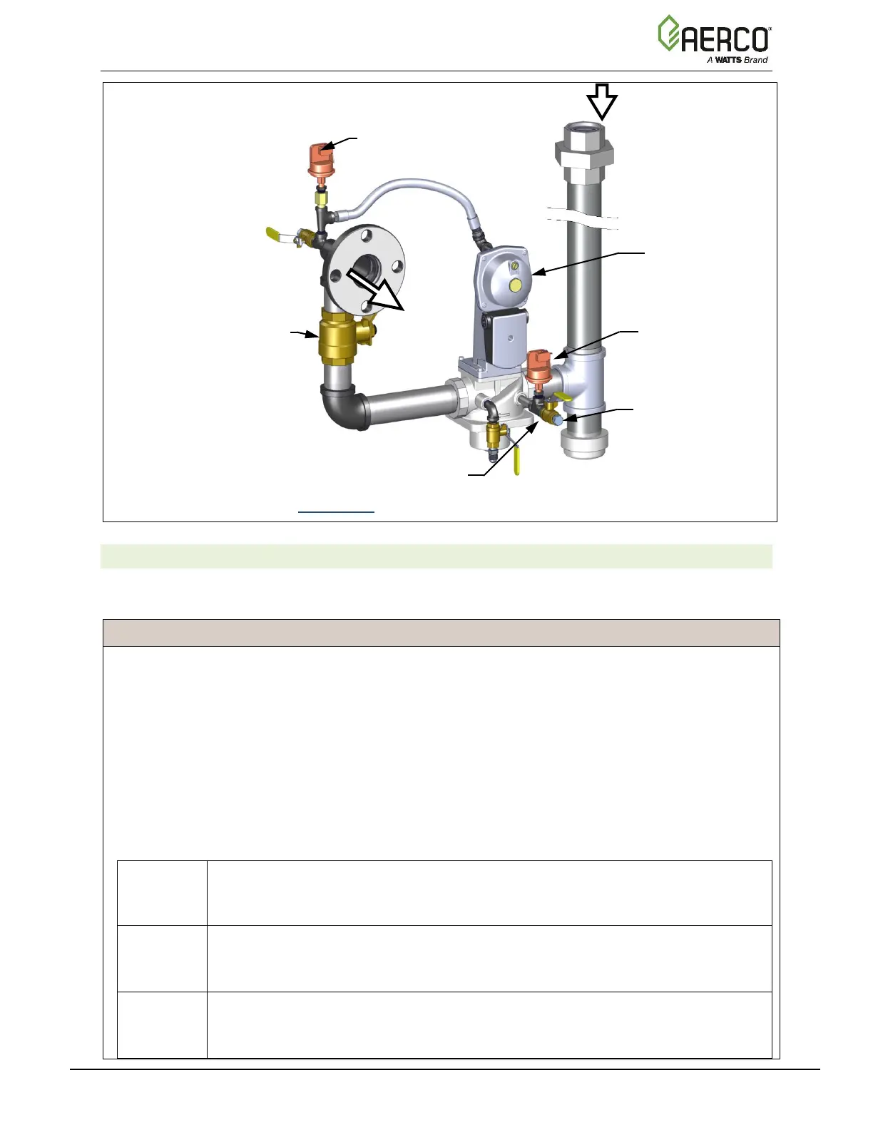
Figure 5-1c: BMK2500 LOW Gas Pressure Test Components
5.2.2 Low Gas Pressure Test: BMK3000 – 6000 Only
To simulate a low gas pressure fault on BMK3000 – 6000 units, refer to Figure 5-2a, 5-2b, and
5-2c below, and perform the following steps:
LOW Gas Pressure Test Instructions: BMK3000 – 6000 Only
1. Close the external gas supply ball valve upstream of the unit (not shown).
2. Remove the front panel from the boiler to access the gas train components.
3. Locate the port on the top of the Low Gas Pressure switch and loosen the screw inside a few turns
to open it. Do not remove this screw completely. Alternatively, you can remove the 1/4-inch plug
shown in Figure 5-2a and 5-2b and install a hose barb fitting in that location.
4. Attach one end of the plastic tubing to the port or barb fitting and the other end to a 0 – 16” W.C. (0
– 4.0 kPa) manometer.
5. Apply the reading of the manifold pressure taken in Step 22 of Section 4.4.1 (Natural Gas units) or
Step 22 of Section 4.4.2 (Propane units) and plug it into the following formula, which calculates the
minimum allowable gas pressure:
FM Natural Gas pressure →____ x 0.5 + 0.7 = ______ min gas pressure
DBB Natural Gas pressure →____ x 0.5 + 1.6 = ______ min gas pressure
Propane Gas pressure →_____ x 0.5 + 0.6 = _______ min gas pressure
FM Natural Gas pressure →____ x 0.5 + 0.6 = ______ min gas pressure
DBB Natural Gas pressure →____ x 0.5 + 0.6 = ______ min gas pressure
Propane Gas pressure → ____ x 0.5 + 1.1 = ______ min gas pressure
FM Natural Gas pressure →____ x 0.5 + 0.9 = ______ min gas pressure
DBB Natural Gas pressure →____ x 0.5 + 0.9 = ______ min gas pressure
Propane Gas pressure → ____ x 0.5 + 1.6 = ______ min gas pressure
LOW GAS PRESSURE BALL VALVE
1/4” NPT PLUG
Install manometer
here for LOW gas
pressure fault test.

 Loading...


