Figure 3-1e: BMK5000-6000: SSOV Location (P/N 22330-1 shown)
3. The Auxiliary Delay occurs for a configurable length of time and the Delayed Interlocks are closed.
4. Once all required safety device switches are closed, a purge cycle is initiated and the following
events occur:
a. The Blower relay energizes and turns on the blower.
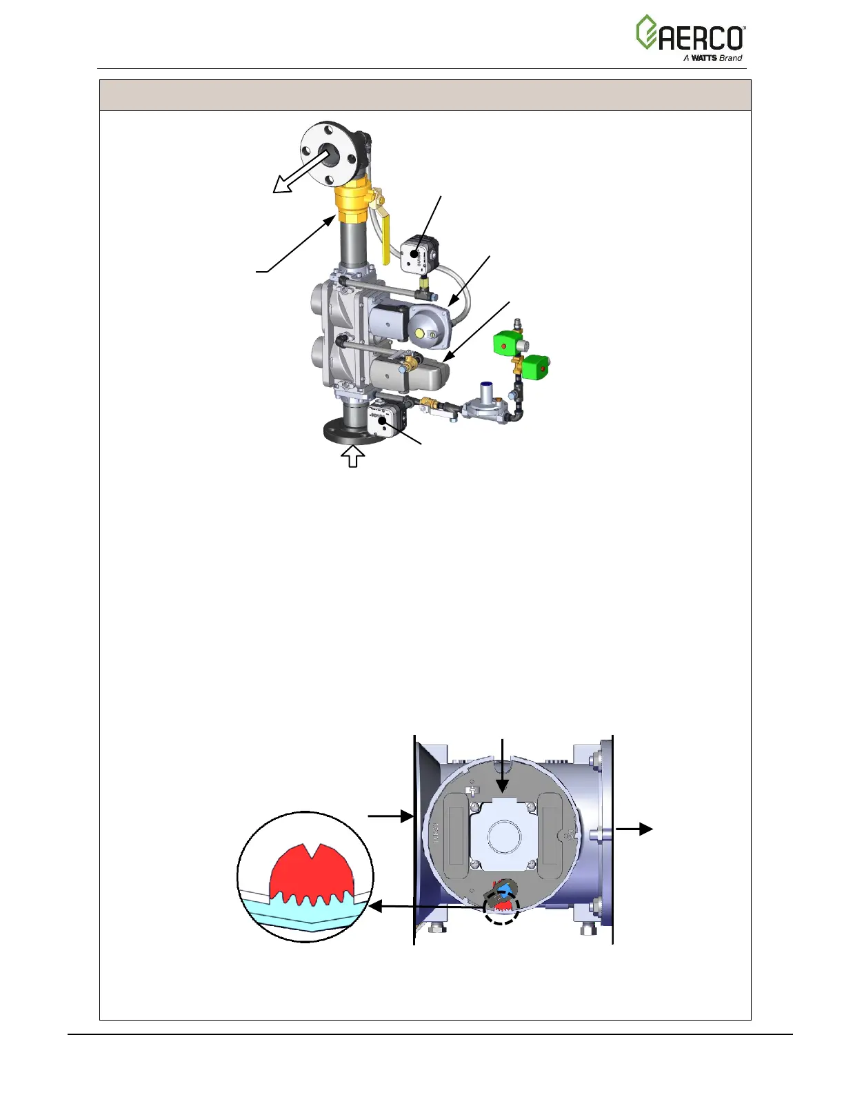
b. The Air/Fuel Valve rotates to the full-open purge position and closes purge position
switch. The dial on the Air/Fuel Valve (Figure 3-2a and 3-2b) will read 100 to indicate
that it is full-open (100%).
c. The Fire Rate bargraph on the Controller’s front face shows 100%.
Figure 3-2a: BMK750 & 1000 Air/Fuel Valve in Purge Position

 Loading...


