8-4 | CFW-11
(1) Steady state rated current in the following conditions: indicated switching frequency.
- For operation with switching frequency of 2.5 kHz (only models 242 A and 312 A), a derating of 10 % must be applied to the current values specified
in Table 8.1 on page 8-2.
- For frame sizes F and G (exept model 760 A) operating with switching frequency of 5 kHz, it is necessary to reduce the rated output current according
to Table 8.3 on page 8-5.
- It is not possible to use the models of frame sizes F, G and H of the CFW-11 inverter with switching frequency of 10 kHz.
Ambient temperature around the inverter as specified in the table.
40 ºC (104 °F) to 45 ºC (113 °F) for frame size G (only model 720 A): 2 % derating of current for each degree Celsius above the maximum temperature
specified in the item above.
40 ºC (104 °F) to 45 ºC (113 °F) for frame sizes G (only model 760 A) and H: 1 % derating of current for each degree Celsius above the maximum
temperature specified in the item above.
45 °C (113 °F) to 55 °C (131 °F) for frame sizes F, G and H: 2 % derating of current for each degree Celsius above the maximum temperature specified
in the item above. Air relative humidity: 5 % to 95 % non-condensing.
Altitude: 1000 m (3.300 ft). Above 1000 m up to 4000 m (3.300 ft to 13.200 ft), the output current must be reduced by 1 % for each 100 m above
1000 m. From 2000 m to 4000 m (6.600 ft to 13.200 ft) above sea level - maximum voltage derating of 1.1 % for each 100 m (330 ft) above 2000
m (6.600 ft).
Environment with pollution degree 2 (as per EN50178 and UL508C).
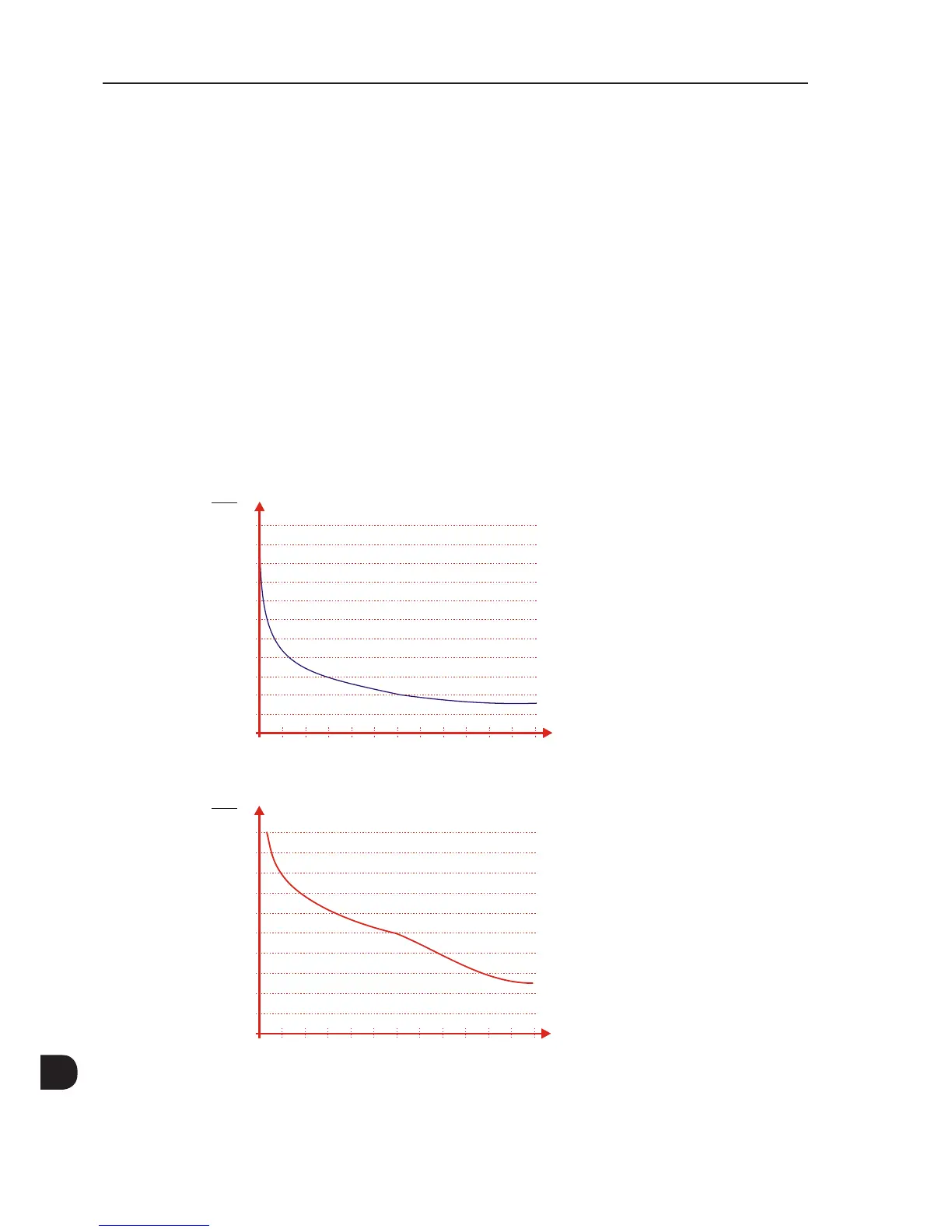
(2) One overload each 10 minutes. Table 8.1 on page 8-2 contains just two points of the overload curve (activation time of 1 min and 3 s). The complete
overload curves of the IGBTs for ND and HD are presented below.
Depending on the inverter operational conditions such as surrounding air temperature and output frequency, the maximum time for operation of the
inverter with overload may be reduced.
(3) The motor outputs are only for guiding purposes for WEG motor 460 V, 4 poles. The proper sizing must be done according to the rated current of the
motors used.
(4) The specified dissipated powers are valid for rated operating conditions, that is, for rated output current and switching frequency.
(5) The dissipated powers for flange mounting correspond to the total losses of the inverter minus the losses on the power modules (IGBT and rectifier).
2.0
1.9
1.8
1.7
1.6
1.5
1.4
1.3
1.2
1.1
1.0
0.9
0 10 20 30 40 50 60 70 80 90 100 110 120
I
o
I
nom ND
∆ t (s)
(*) Attention!
One overload each
10 minutes.
(*)
(a) IGBTs overload curve for the Normal Duty (ND) cycle
2.0
1.9
1.8
1.7
1.6
1.5
1.4
1.3
1.2
1.1
1.0
0 10 20 30 40 50 60 70 80 90 100 110 120
I
o
I
nom HD
∆ t (s)
(*) Attention!
One overload each
10 minutes.
(*)
(b) IGBTs overload curve for the Heavy Duty (HD) cycle
Figure 8.1 - (a) and (b) - IGBT overload curves for ND and HD use