8
MOTOR CONTROL
P134P145
P136
P142
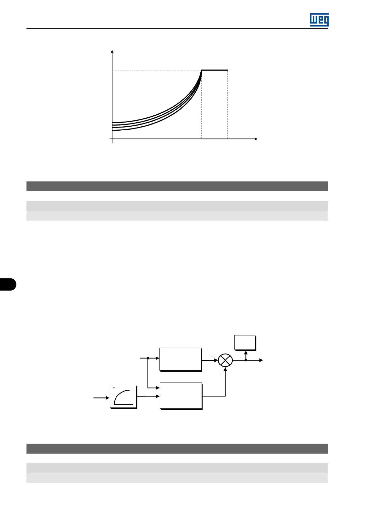
Output
frequency (Hz)
Output
voltage (%)
Figure 8.16: Torque boost region for quadratic V/f control mode
P137 - Automatic Torque Boost
Range: 0.0 to 30.0 %
Properties: V/f
Description:
The automatic torque boost compensates the voltage drop in the stator resistance because of active current.
Look at Figure 8.12 on page 8-19, where variable IxR corresponds to the automatic torque boost action on the
modulation index defined by V/f curve.
P137 actuates similarly to P136, but the value set is applied proportionally to the output active current in relation to
the maximum current (2 x P295).
The setting criteria of P137 are the same as those of P136, that is, set the value as low as possible for the motor
start and operation at low frequencies, because values above those increase the losses, heating and overload of
the motor and inverter.
The block diagram of Figure 8.17 on page 8-22 shows the automatic compensation action IxR responsible for the
increment of the voltage in the ramp output according to the increase of the active current.
I x R
P136
P007
P139
I x R
automatic
P137
Voltage
applied on
the motor
Output
active current
Frequency reference
Figure 8.17: Block diagram of the automatic torque boost
P138 - Slip Compensation
Range: -10.0 to 10.0 %
Properties: V/f
Description:
Parameter P138 is used in the motor slip compensation function, when set for positive values. In this case, it
8-22 | Micro Mini Drives