8
MOTOR CONTROL
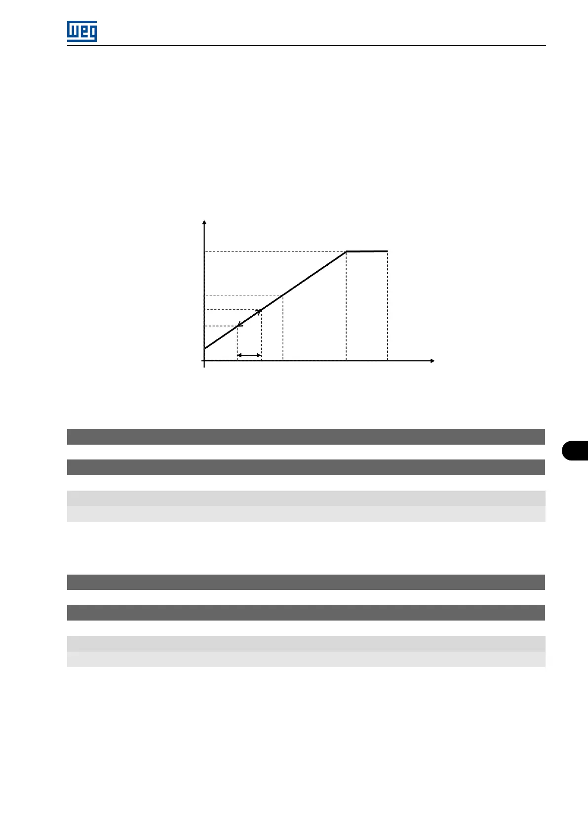
compensates the speed drop due to the application of load on the shaft and, consequently, the slip. Thus, it
increments the output frequency (Δf) considering the increase of the motor active current, as shown in Figure 8.18
on page 8-23. In Figure 8.12 on page 8-19 this compensation is represented in the variable f
Slip
.
The setting in P138 allows regulating with good accuracy the slip compensation by moving the operation point on
the V/f curve, as shown in Figure 8.18 on page 8-23. Once P138 is set, the inverter is able to keep the frequency
constant even with load variations.
Negative values are used in special applications where you wish to reduce the output frequency considering the
increase of the motor current.
Eg.: load distribution in motors driven in parallel.
P134P145P146
P136
P143
P142
∆f
Output
frequency (Hz)
Output
voltage (%)
Figure 8.18: Slip compensation in an operation point of the standar V/f curve
P142 - Maximum Output Voltage
P143 - Intermediate Output Voltage
Range: 0.0 to 100.0 %
Properties: cfg, V/f
Description:
These parameters allow adjusting the inverter V/f curve together with its orderly pairs P145 and P146.
P145 - Field Weakening Speed
P146 - Intermediate Frequency
Range: 0.0 to 400.0 Hz
Properties: cfg, V/f
Description:
These parameters allow adjusting the inverter V/f curve together with its orderly pairs P142 and P143.
The V/f curve can be adjusted in applications where the motor rated voltage is smaller than the power supply
voltage, for example, a power supply of 220 V with motor of 200 V.
The adjustment of the V/f curve is necessary when the motor has a frequency different from 50 Hz or 60 Hz, or when
a quadratic approximation is desired for energy saving in centrifugal pumps and fans, or in special applications:
when a transformer is used between the inverter and the motor or the inverter is used as a power supply.
Micro Mini Drives | 8-23