Product description
68
Operating instructions – AC SMART
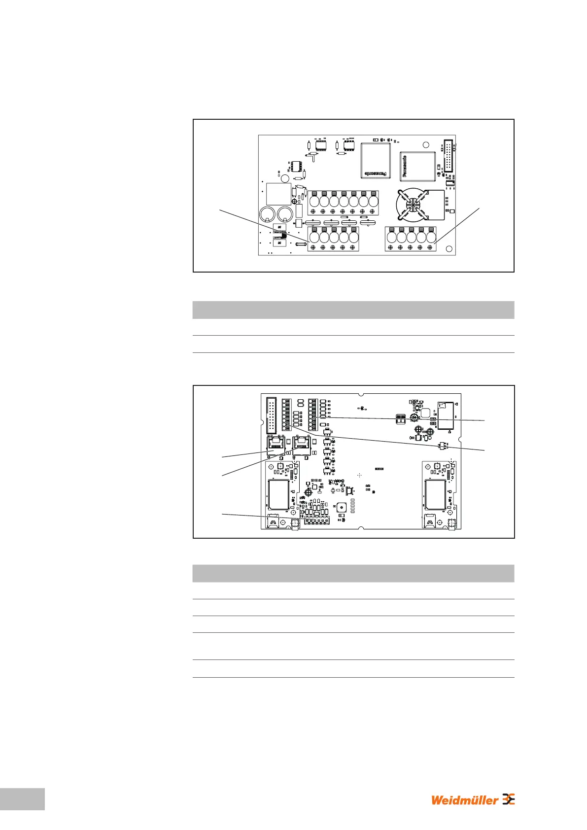
Power board in the housing base part
IN
OUT
Image 3.5
Identication Description
IN Connection terminal supply line
OUT Only PLUG variation; charging cable connection terminal
Control board in the housing cover
X1
X2
X3
X6
X5
Image 3.6
Identication Description
X1 Only PLUG variation: plug-in connector to connect the CP conductor
X2 RJ45 Ethernet interface (VALUE and ADVANCED only)
X3 RJ45 Ethernet interface
X5
8-pin connection for 4 x digital outputs, 1 x serial interface (RS485
Modbus-RTU) and 2 x ground
X6
8-pin connection for 5 x digital inputs, 2 x 12 V supply and 1 x ground