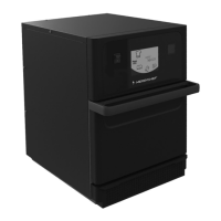
3.
■
T
ap out the smaller, pre-perforated knock-out in the floor panel of
the combi oven, at the position indicated.
■
Insert the cable gland in the knock-out then feed the connecting ca-
ble for the energy optimization system through the cable gland into
the wiring compartment of the combi oven.
■
Route the connecting cable to the SIB and fix it in the wiring com-
partment, e. g. using cable ties to attach it to an existing wiring har-
ness.
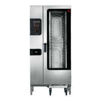
4.
Remove the wire link between the terminals (B) and (C) on terminal
block -X37 (2).
5.
Connect the terminals (A), (B), (C) and (D) of terminal block -X37 (2)
to the energy optimization system.
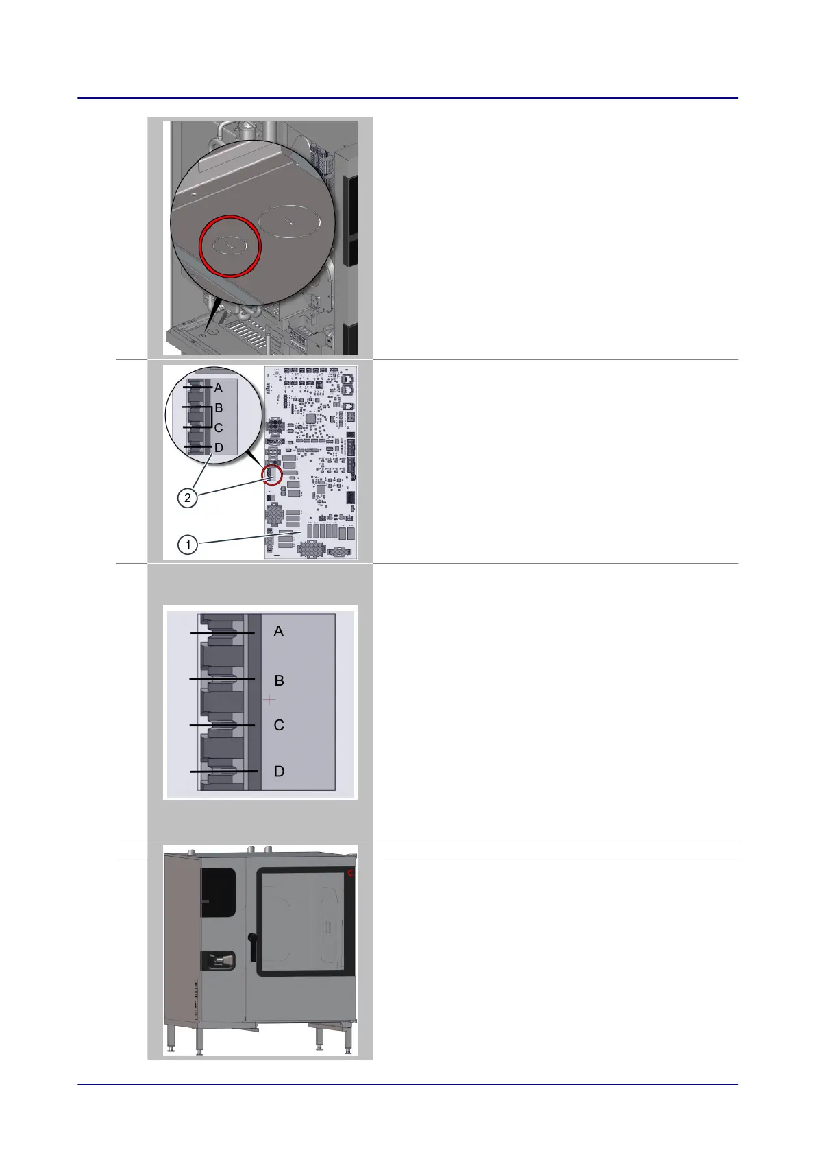
Terminal Combi oven
Energy optimization
system
A
Phase, when combi oven is
on
-
B
Phase, when combi oven
heating element is on
Switching relay
C
Heater enable, B and C
must be connected by
switching relay in the ener-
gy optimization system in
order to enable heating
Switching relay
D
Neutral -
6.
Refit the side panel on the combi oven.
7.
Put the combi oven and energy optimization system into operation.
6 Installation
Installation manual 44