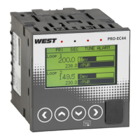
Pro-EC44 2-Loop Graphical Profile Controller & Recorder
Pro-EC44 Product Manual - 59540-2 September 2014 Page 168
Alarm 5 Input Source Value Source
Dec 6207 22591 45182
RW
0 Input 1
Hex 183F 583F B07E
1 Input 2
2 Aux A Input
3 Control Loop 1 Primary Power
4 Control Loop 1 Secondary Power
5 Control Loop 2 Primary Power
6 Control Loop 2 Secondary Power
7 Loop 1
8 Loop 2
Alarm 5 Type Value Alarm 5 Type
Dec 6208 22592 45184
RW
0 Unused
Hex 1840 5840 B080
1 Process High Alarm
2 Process Low Alarm
3 Deviation Alarm (SP-PV)
4 Band Alarm
5 Input Rate of Change
6 Input/Sensor Break Alarm
7 Loop Alarm
10 % memory used
11 High Power Alarm
12 Low Power Alarm
Alarm 5 Value Value At Which Alarm 5 Activates
Dec 6209 22593 45186
RW
Limited by input scaling for alarm types 1 to 4.
Not used for alarms 5, 6 or 7.
0 to 100% for alarms 10 to 12.
Hex 1841 5841 B082
Alarm 5 Rate of Change Value Process Variable Rate of Change Alarm Threshold
Dec 6214 22598 45196
RW
Value for Rate of Change Alarm. Alarm 5 activates when PV
change exceeds this level. From 0.0 to 99999
Hex 1846 5846 B08C
Alarm 5 Hysteresis Alarm 5 Hysteresis Value
Dec 6210 22594 45188
RW
Deadband value (on “safe” side of alarm), through which signal
must pass before Alarm 5 deactivates.
Limited by the input scaling span
Hex 1842 5842 B084
Alarm 5 Inhibit Enable/disable Value Alarm 5 Power-up/Setpoint Change Inhibit
Dec 6211 22595 45190
RW
0 Disabled
Hex 1843 5843 B086
1 Enabled
Alarm 5 Status Value Alarm 5 Status
Dec 6212 22596 45192
RO
0 Inactive
Hex 1844 5844 B088
1 Active
Alarm 5 Inhibit Status Value Alarm 5 Inhibit Status
Dec 6213 22597 45194
RO
0 Not Inhibited
Hex 1845 5845 B08A
1 Inhibited
Alarm 5 Label Main Language Name For Alarm 5 In Status Screen
Dec 6215 22599 45198
RW
8 ASCII characters replacing the title "Alarm 5" in alarm status
screens when main display language is used, read/written with
Modbus functions 16 or 23. Valid characters are 0 to 9, a to z, A
to Z, plus ß ö ( ) - and _.
Hex 1847 5847 B08E
 Loading...