15
Western Digital Hard Disk Drive OEM Specification
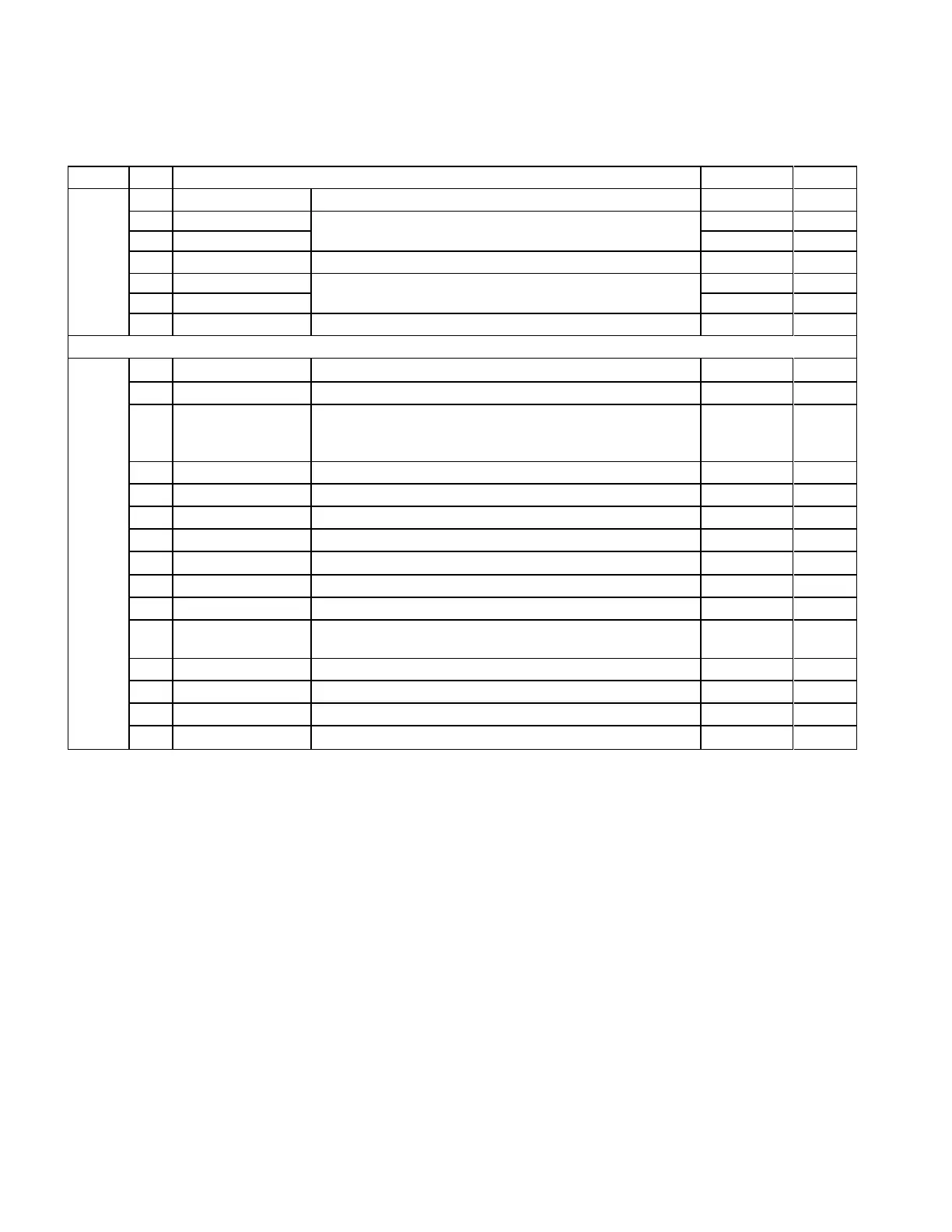
6.1.2 Signal Definition (SATA)
SATA has receivers and drivers to be connected to TX+/- and RX +/- Serial data signal.
Defines the signal names of I/O connector pin and signal name.
Plug Connector Pin Definition
Differential signal A from Phy
Differential signal B from Phy
Key and spacing separate signal and power segments
Not used (P1 and P2 tied internally)
Not used (P1 and P2 tied internally)
Reserved* or
PWDIS* (option)
Not used (P1, P2, and P3 tied internally)
or
Enter/Exit Power Disable (option)
5V power, Precharge, 2nd Mate
Support staggered spin-up and LED activity
VDih max=2.1V
12V power, Precharge, 2nd mate
Table 11 Interface Connector Pins and I/O Signals
* SATA Specification Revision 3.1 and prior revisions assigned 3.3V to pins P1, P2, and P3. In addition, device plug
pins P1, P2, and P3 were required to be bused together. In the standard configuration of this product, P3 is
connected with P1 and P2 and this product behaves as SATA 3.1 or prior version product in a system designed to
SATA 3.2 system that does not support the 3.3 feature. For product with the optional SATA 3.3 Power Disable
Feature supported, P3 is now assigned as the POWER DISABLE CONTROL PIN. If P3 is driven HIGH (2.1V-3.6V
max), power to the drive circuitry will be disabled. Drives with this optional feature WILL NOT POWER UP in systems
designed to SATA Spec Revision 3.1 or earlier because P3 driven HIGH will prevent the drive from powering up.